Note 03 of 04: 笔记 03 / 04:Two Power Systems and the Relay-Switched Laser两套电源与继电器控制的激光
On day two of the NUEDC contest the grey-scale sensors' 5 V outputs killed the MSPM0 core board. Working back from that board through the datasheet and the car's two power systems, a buck plus LDO chain for the MSPM0 and three separately switched LM2596 bucks for the aiming side, ends at the relay that lights the laser when its K230 GPIO goes low.电赛第二天,灰度传感器的 5 V 输出烧掉了 MSPM0 核心板。从这块板子出发,翻数据手册,再顺着车上的两套电源往下走:MSPM0 这边是降压加 LDO,瞄准那边是单独开关的三颗 LM2596,最后走到那个让激光在 K230 的 GPIO 拉低时才亮的继电器。
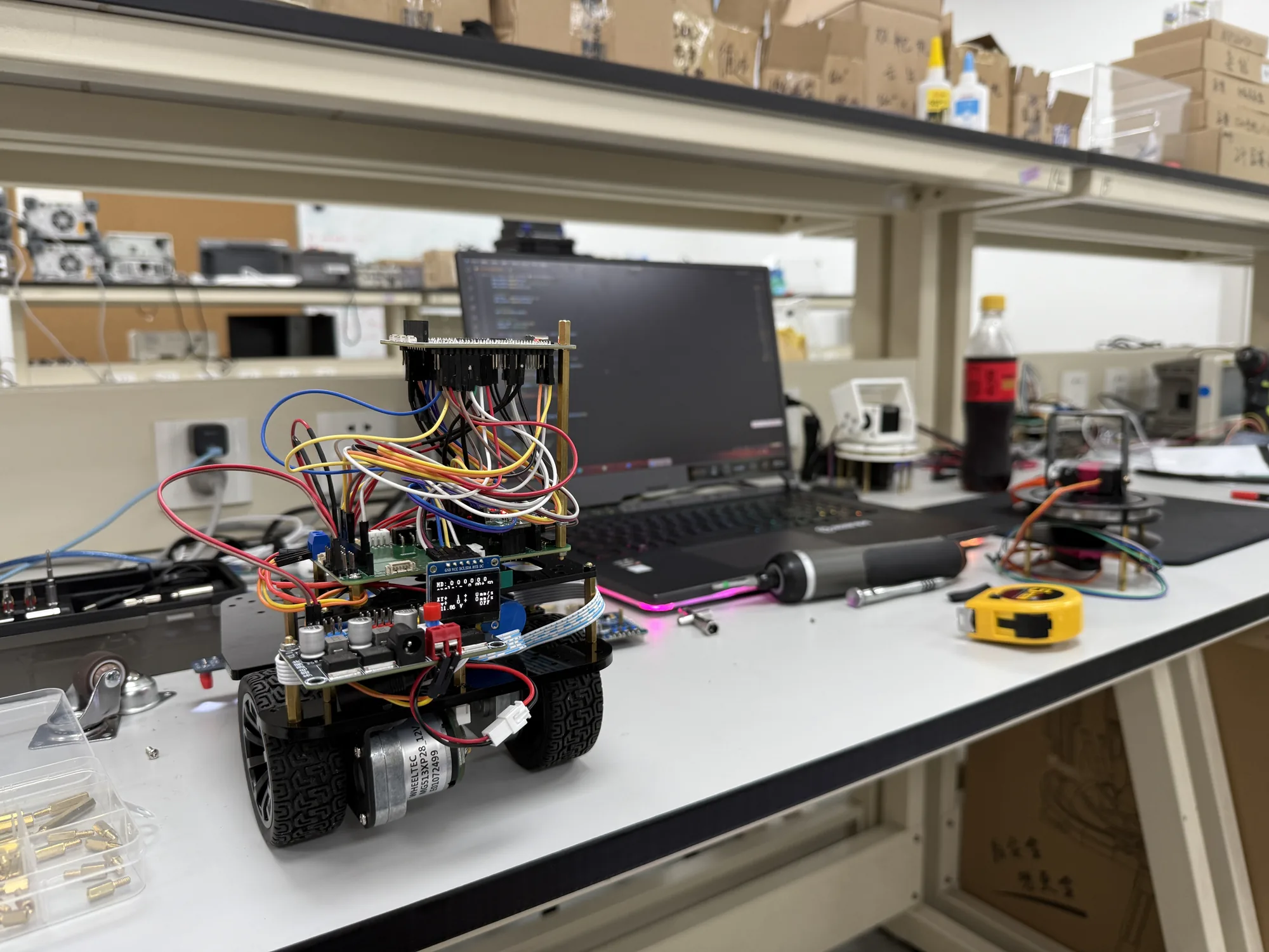
On day two the main controller burned. The grey-scale sensor bar was running from 5 V at the time, so its outputs went up to 5 V, and they went straight into the MSPM0's pins with nothing in between. The C07A core board did not survive. The spare we had was barely usable; I ran flying wires on it so we could keep debugging, a new chip went out by SF Express rush delivery and only arrived early on day four, and the last twelve hours were chip swapping, soldering and more flying wires. The sensors moved to 3.3 V afterwards. The fix itself was trivial; the board had already cost us the better part of two days of worry and a courier bill.
第二天,主控板烧了。灰度传感器条那时接的是 5 V,输出的高电平也就到 5 V,这些输出直接接进 MSPM0 的引脚,中间什么都没有。C07A 核心板就这么没了。手上的备用板几乎不能用,我在上面飞线,凑合着接着调;新芯片顺丰加急寄过来,第四天清晨才到,最后十二个小时都在换芯片、焊接、继续飞线。传感器后来改到了 3.3 V 上。改这一下不费什么事,那块板子却已经搭进去将近两天的提心吊胆,外加一单加急快递。
5 V Outputs into 3.3 V Pins5 V 输出进 3.3 V 引脚
The MSPM0G350x datasheet is blunt about this. Its absolute maximum ratings allow a common-tolerance pin at most VDD + 0.3 V, which is 3.6 V on a 3.3 V supply, and limit the current through any pin's protection diodes to ±2 mA. A 5 V high level is well over that line, on six pins at once, every time the sensors saw black. Absolute maximum ratings are the line beyond which the chip promises nothing.
MSPM0G350x 的数据手册在这件事上写得很直白:绝对最大额定值里,普通耐压的引脚最多只能承受 VDD + 0.3 V,3.3 V 供电时就是 3.6 V;任何引脚保护二极管上的电流,限制在 ±2 mA 以内。5 V 的高电平远远越过这条线,而且是六个引脚一起,传感器每压一次黑线就来一次。绝对最大额定值是一条红线,过了线,芯片就什么都不保证了。
The same table lists a second class of pin, and that is where the story gets a little cruel. The 5 V tolerant open-drain pins, ODIO, may see up to 5.5 V, and TI has a 5 V interface design built on exactly those, with external pull-ups to 5 V. On the MSPM0G3507 they are PA0 and PA1. On our car, PA0 and PA1 carried the MPU6050's I2C, a bus that runs at 3.3 V anyway. The only two pins on the chip that could have taken a 5 V sensor output were the two not connected to one.
同一张表里还有另一类引脚,故事到这里就有点残忍了。5 V 耐压的开漏引脚叫 ODIO,最高能接 5.5 V,TI 专门有一份 5 V 接口的设计示例,用的就是这类引脚,外面接上拉到 5 V。MSPM0G3507 上的 ODIO 是 PA0 和 PA1。我们车上,PA0、PA1 接的是 MPU6050 的 I2C,这条总线本来就跑在 3.3 V。整颗芯片上唯二扛得住 5 V 传感器输出的两个引脚,偏偏没接传感器。
Moving the sensors to 3.3 V brings their output high level down to the MCU's own supply. When a sensor genuinely has to run at 5 V, the usual options are a series resistor to keep the diode current under that 2 mA, a resistor divider, a level-shifting buffer, or an ODIO pin with a pull-up. Every one of them costs a few cents, and any one of them would have saved a core board and an SF Express rush order.
传感器挪到 3.3 V 以后,输出高电平就和单片机自己的电源对齐了。要是传感器确实得跑在 5 V,常见的办法有几种:串一个电阻,把保护二极管上的电流压在 2 mA 以内;用电阻分压;加一颗电平转换的缓冲器;或者把信号接到带上拉的 ODIO 引脚上。哪一种都花不了几毛钱,随便用上一种,就能省下一块核心板和一单顺丰加急。
MSPM0 Side and Aiming Side主控与瞄准两套电源
Which rail a sensor hangs on is a question about the whole car's power, and the car has two systems hanging off one 12 V lithium battery. Problem E requires it: the MSPM0 controller and the aiming module must each have their own power switch, with an LED showing each board's state. Every module on both systems was bought ready-made.
传感器挂在哪条电源轨上,说到底是整车供电的问题。车上是一块 12 V 锂电池底下挂着两套电源,这是 E 题的规定:MSPM0 控制板和瞄准模块要用两个独立的开关分别供电,每块板子还要有一个发光管指示供电状态。两套上的模块,全是买来的成品。
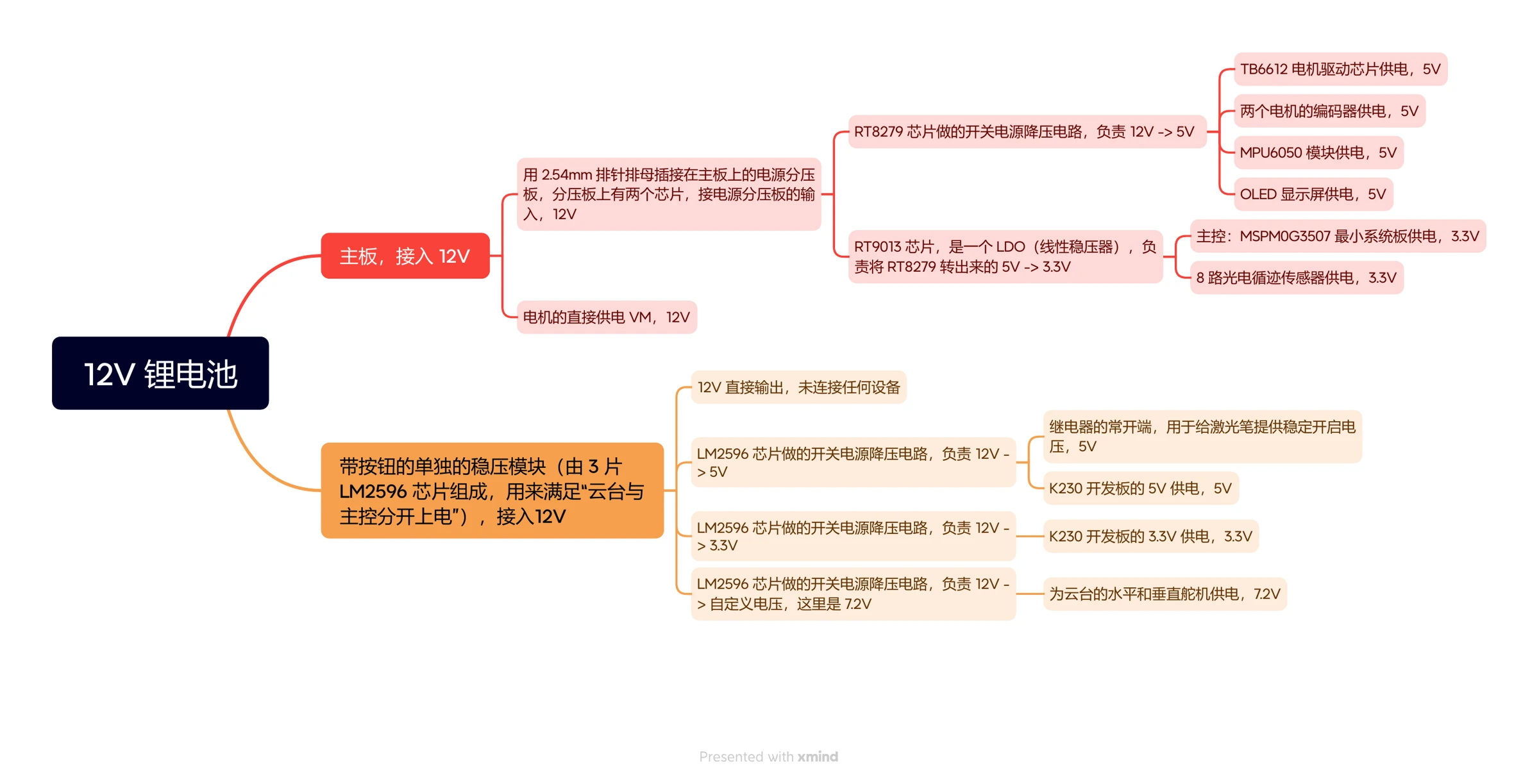
On the MSPM0 side, the battery's 12 V goes straight to the motor driver's VM pin. A small divider board plugs onto the main board through 2.54 mm headers and carries two parts: an RT8279, a 36 V, 5 A step-down converter that makes 5 V for the TB6612's logic, the two encoders, the MPU6050 and the OLED, and an RT9013 LDO that takes that 5 V down to 3.3 V for the core board and, after day two, the sensor bar. The buck handles the big drop from 12 V efficiently but leaves switching ripple on its output; the LDO after it gives up a little efficiency for a quieter 3.3 V, and the microcontroller sits at the very end of that chain.
主控这一路,电池的 12 V 直接送到电机驱动的 VM 脚。主板上用 2.54 mm 排针插着一块小小的分压板,板上两颗芯片:RT8279 是一颗 36 V、5 A 的降压芯片,出 5 V 给 TB6612 的逻辑部分、两个编码器、MPU6050 和 OLED;RT9013 是一颗 LDO,把这 5 V 再降成 3.3 V,给核心板,第二天以后也给灰度传感器条。从 12 V 往下降一大截,交给开关降压效率高,可输出上带着开关纹波;后面再串一个 LDO,牺牲一点效率,换一个更干净的 3.3 V,单片机就挂在这条链的最末端。
The aiming side has its own bought module with a power button, built from three LM2596 bucks fed from the same 12 V, plus a fourth output that just passes 12 V through and is left unconnected. The LM2596 is a 3 A buck converter. One makes 5 V for the K230 board and, through the relay, for the laser; one makes 3.3 V for the K230's 3.3 V rail; the third is set to 7.2 V for the two gimbal servos. Besides satisfying the rule, the split keeps the servos' current steps away from the regulators behind the microcontroller: when a servo jerks, the load step lands on its own LM2596, not on the RT8279 and RT9013. The two systems still share the battery's negative terminal, which is what lets any signal cross between the boards at all.
瞄准这一路单独用一块带按钮的成品稳压模块,上面是三颗 LM2596,同样从 12 V 取电,第四路输出直接把 12 V 引出来,没接任何东西。LM2596 是一颗 3 A 的降压芯片。一颗出 5 V,给 K230 开发板,也经过继电器给激光笔;一颗出 3.3 V,给 K230 的 3.3 V;第三颗调到 7.2 V,给云台的两个舵机。这样分开,除了满足规定,也让舵机的电流跳变落不到单片机身后的稳压芯片上:舵机猛地一动,突然多扛电流的是它自己那颗 LM2596,不是 RT8279 和 RT9013。两套电源仍然共用电池的负极,板子之间的信号能传过去,靠的就是这根共地。
Relay and Laser继电器与激光
The laser is switched by a relay. Its control input is wired to K230 GPIO 2 so that a high level pulls the coil in, and the laser's positive lead sits on the normally closed contact, with its 5 V from the aiming side's LM2596. That is why the code reads backwards at first glance. K230.PY writes LASER.value(1) right after start-up and again in the finally block on exit: the coil pulls in, the normally closed contact opens, and the laser goes dark. When the target is centred it writes LASER.value(0): the coil drops out, the contact closes, and the laser lights. A relay's normally closed contact is the one that conducts with no current in the coil.
激光笔由一个继电器开关。继电器的控制端接 K230 的 GPIO 2,高电平时线圈吸合;激光笔的正极接在常闭触点上,5 V 来自瞄准这一路的 LM2596。所以代码乍一看是反着的:K230.PY 一启动就写 LASER.value(1),退出时在 finally 里再写一次,线圈吸合,常闭触点断开,激光灭;靶子居中时写 LASER.value(0),线圈释放,触点合上,激光亮。继电器的常闭触点,就是线圈里没有电流时导通的那一组。
With the laser on the normally closed side, its resting state is lit. Whenever nothing drives the coil, the laser is on: from power-up until the K230 has configured GPIO 2 as an output and the script reaches its first LASER.value(1), and again whenever the K230 resets and the pin stops driving high. The coil, in turn, has to stay pulled in for every moment the laser is meant to be dark. The problem itself warns that the 405 nm blue-violet laser must never reach eyes or skin, and by that standard the normally open contact is the safer default: no drive, no light. Once the contest code is running the two wirings behave the same; the difference lives in the seconds before it starts and after it stops.
激光接在常闭这一侧,亮就成了它的默认状态。只要没有东西在驱动线圈,激光就亮着:从上电开始,到 K230 把 GPIO 2 配成输出、脚本跑到第一句 LASER.value(1) 为止,它是亮的;K230 一复位,引脚不再输出高电平,它也是亮的。反过来,激光该灭的每一刻,线圈都得一直吸着。题目里专门提醒,405 nm 的蓝紫激光千万不能照到眼睛和皮肤,按这个要求,接常开触点才是更稳妥的默认值:不驱动,就不亮。比赛代码跑起来以后,两种接法用着没区别,差别全在它开始之前和停下之后那几秒。
The burned board on day two and the relay on the gimbal turn out to ask the same two things of every signal: which rail it comes from, and which way it falls when nothing is driving it. On a car built entirely from bought modules, answering those two questions for every wire is most of what the circuit design actually is.
第二天烧掉的那块板子,和云台上的那个继电器,问的其实是同样两件事:每一路信号从哪条电源轨上来,没人驱动的时候又停在哪一边。一辆模块全靠买的车,电路设计的大半功夫,就是把每根线的这两个问题答对。