

Media媒体
Board photos, schematic sheets, renders, videos, and test captures stay attached to the projects and engineering stages they document.板卡照片、原理图分页、渲染图、视频和测试截图,都按它们所记录的项目与工程阶段归档。
- Records媒体记录
- 084
- Images图像
- 080
- Videos视频
- 004
- Projects关联项目
- 008
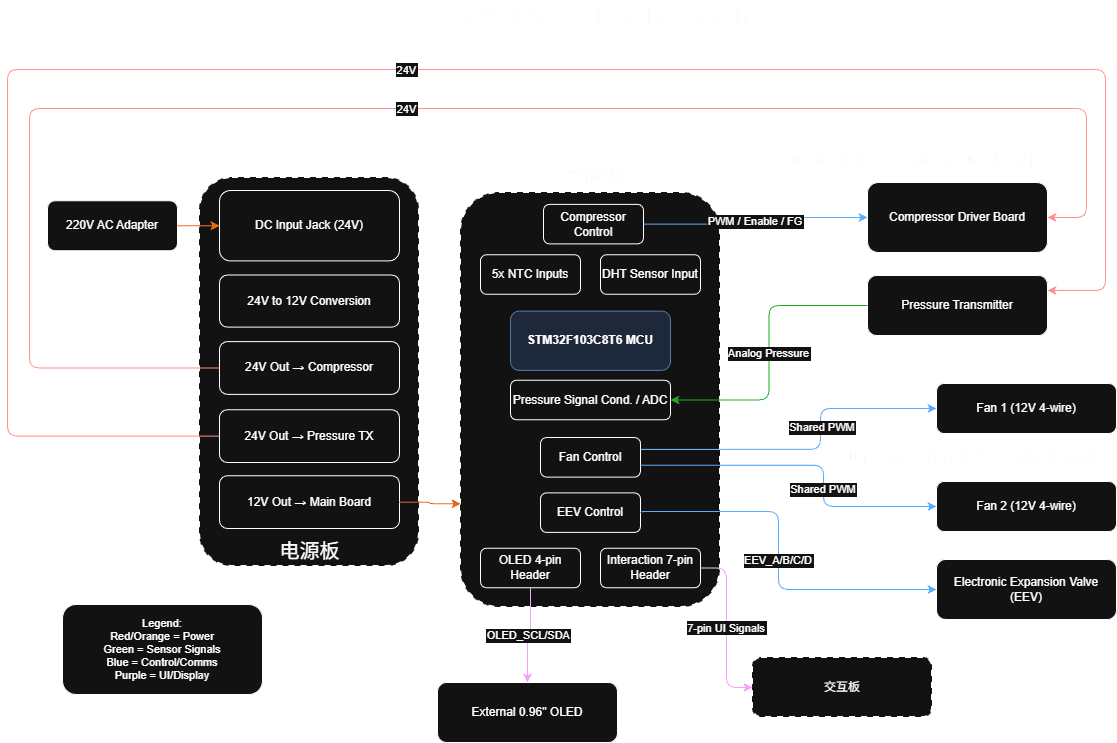
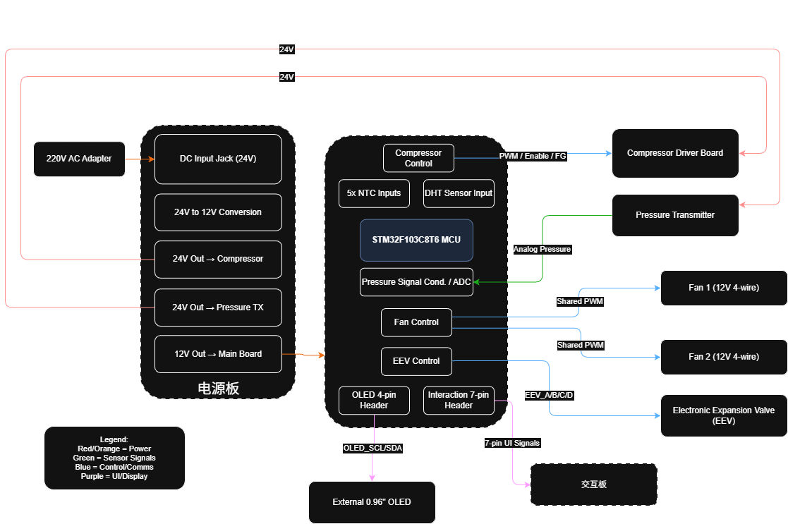
Power and signal routes in the V2.0 ACUnit diagramV2.0 ACUnit 图里的电源与信号路径
The titled V2.0 diagram traces power, sensing, control, display, and user-interface paths across power, main-control, and interaction boards.这张自带 V2.0 标题的图跨分电板、主控板与交互板,追踪电源、传感、控制、显示和用户交互路径。
Media, grouped by project按项目分类的媒体库
Each chapter keeps its source project, engineering context, and records together.每一个分区都把项目来源、工程背景和对应媒体放在一起,不再混成一张总图墙。
Cirro Phase-Change Cooling Controllers卷云相变散热器控制系统
At Juanyun, I independently completed BaseUnit and three-board ACUnit hardware, firmware, and integration, then continued into automatic control and maintenance. The company team performed the later refrigeration tests.在卷云实习期间,我独立完成 BaseUnit 与三板 ACUnit 的硬件、固件和整机联调,随后继续参与自动控制与维护。后期完整制冷测试由公司团队执行。
- Records记录
- 020
- Images图像
- 020
- Videos视频
- 000
- 01.01Image图像
Power and signal routes in the V2.0 ACUnit diagramV2.0 ACUnit 图里的电源与信号路径
The titled V2.0 diagram traces power, sensing, control, display, and user-interface paths across power, main-control, and interaction boards.这张自带 V2.0 标题的图跨分电板、主控板与交互板,追踪电源、传感、控制、显示和用户交互路径。
Project source · Cirro thermal hardware项目来源 · 卷云相变散热系统 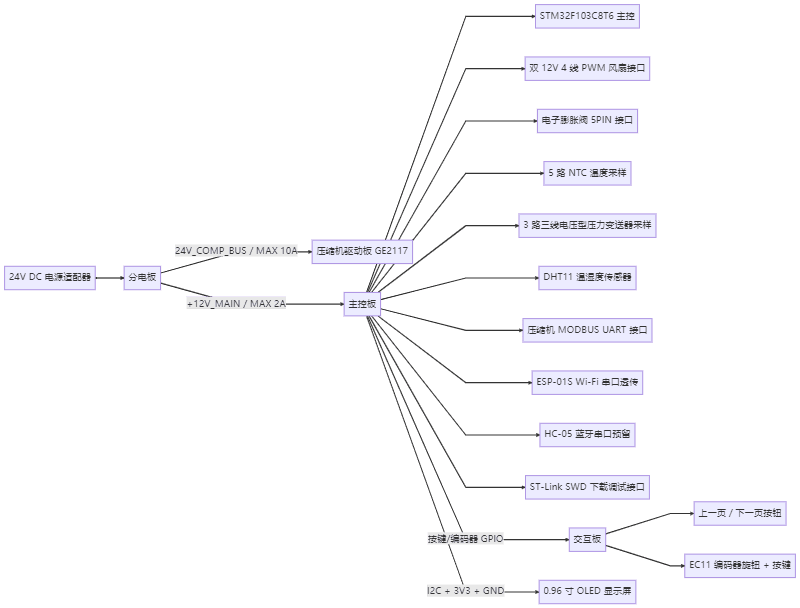 01.02Image图像
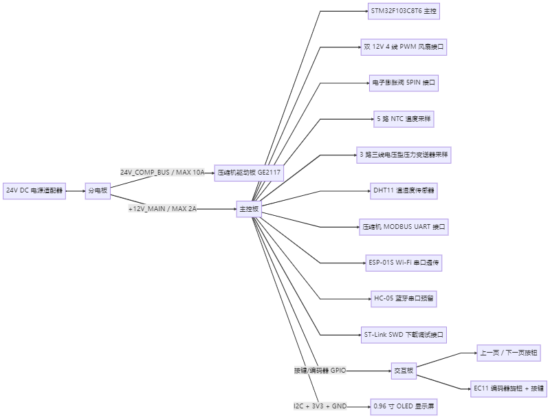
V2.1 ACUnit interface mind mapV2.1 ACUnit 接口思维图
A Chinese branch map listing power buses, STM32, fan, EEV, sensor, UART, wireless, SWD, interaction, and OLED connections around three boards.中文分支图围绕三块板列出电源总线、STM32、风扇、EEV、传感器、UART、无线、SWD、交互与 OLED 连接。
Project source · Cirro thermal hardware项目来源 · 卷云相变散热系统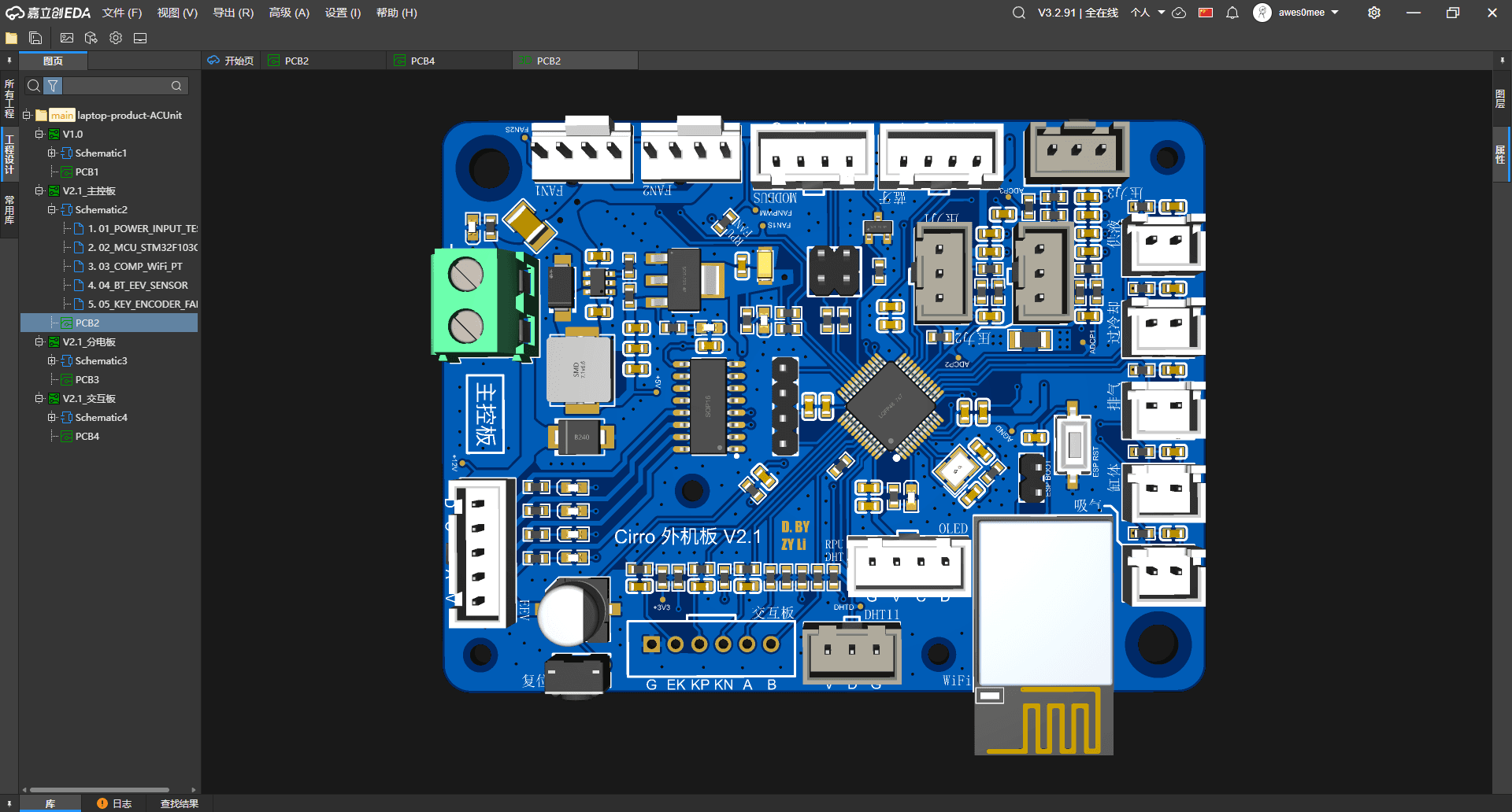 01.03Image图像
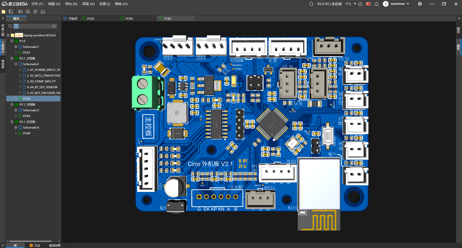
Connectors around the ACUnit main board围住 ACUnit 主控板的连接器
Front-side render with an STM32 package, labeled sensor and display headers, edge connectors, reset, and a Wi-Fi module position.正面渲染可见 STM32 封装、带标签的传感与显示排针、板边连接器、复位键和 Wi-Fi 模块位置。
Project source · Cirro thermal hardware项目来源 · 卷云相变散热系统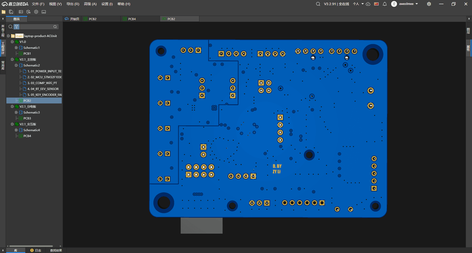 01.04Image图像
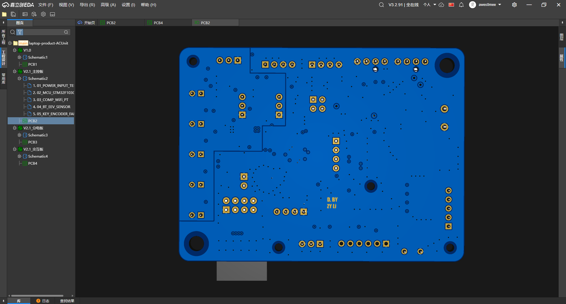
Main-board routing from the back从背面看主控板走线
The back render exposes mounting holes, through-hole pads, vias, and routing that the component-heavy front view hides.背面渲染露出安装孔、通孔焊盘、过孔与走线,补上器件密集正面看不到的部分。
Project source · Cirro thermal hardware项目来源 · 卷云相变散热系统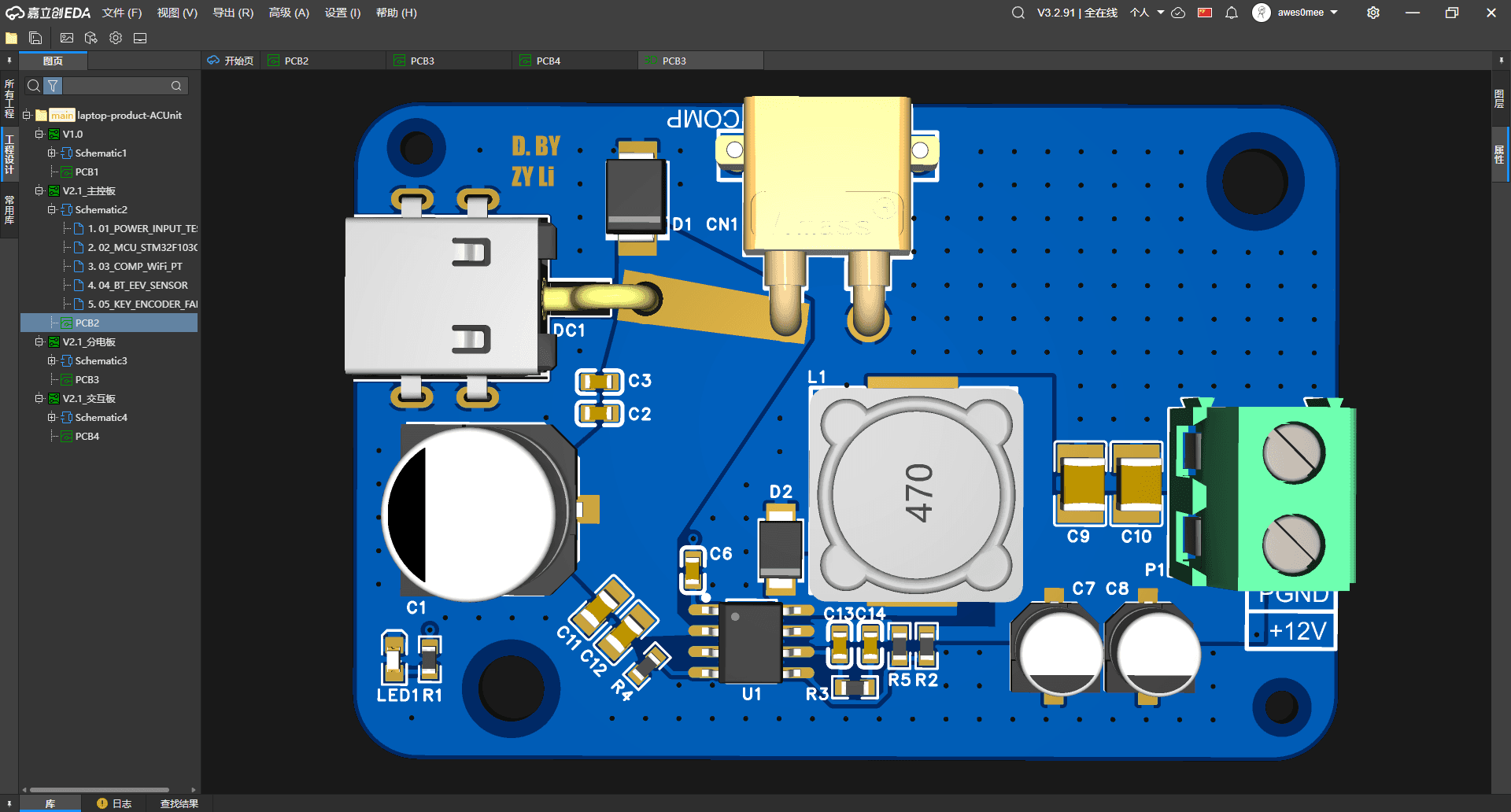 01.05Image图像
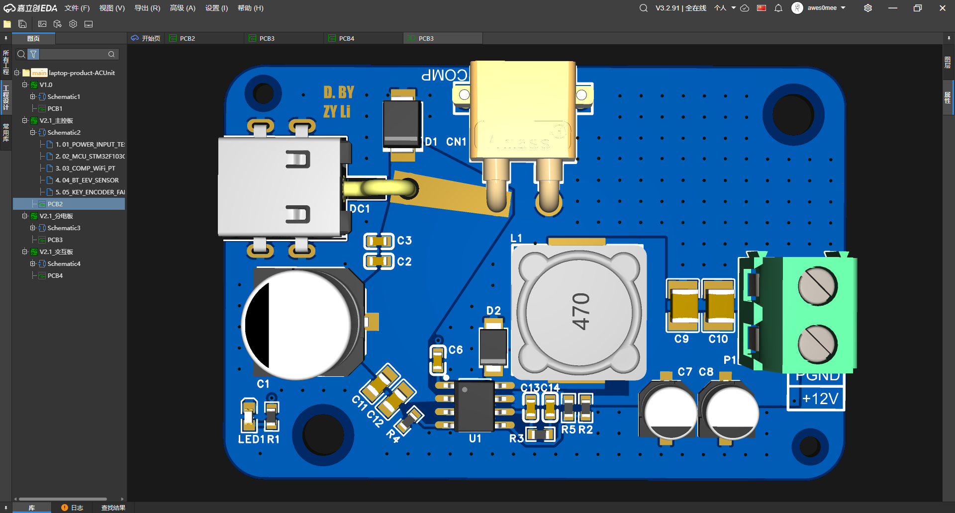
DC input and 12 V terminal on the power board分电板上的 DC 输入与 12 V 端子
Front render grouping a DC jack, blade fuse, conversion components, a 470-marked inductor, and the +12V/PGND screw terminal.正面渲染把 DC 插座、片式保险丝、变换器件、标着 470 的电感与 +12V/PGND 螺钉端子放在一起。
Project source · Cirro thermal hardware项目来源 · 卷云相变散热系统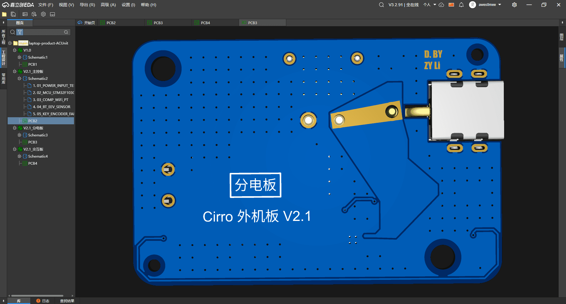 01.06Image图像
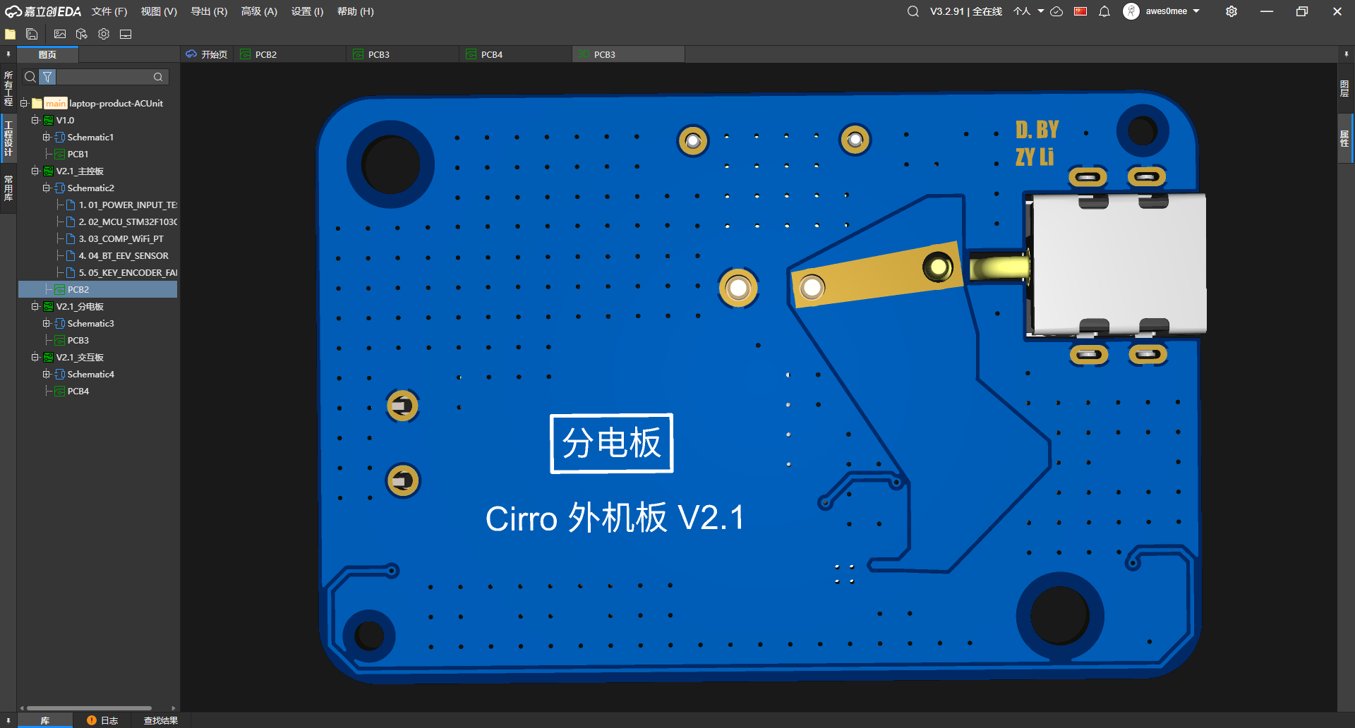
Wide copper on the power-board back分电板背面的宽铜箔
Back-side view of the same board, where broad copper shapes, mounting holes, and the DC-jack connection are visible without component clutter.同一块板的背面视角,宽铜箔、安装孔与 DC 插座连接不再被正面器件遮住。
Project source · Cirro thermal hardware项目来源 · 卷云相变散热系统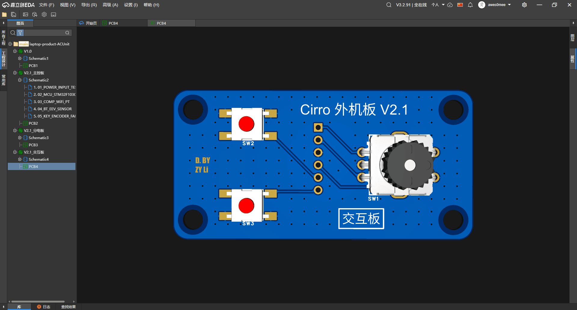 01.07Image图像
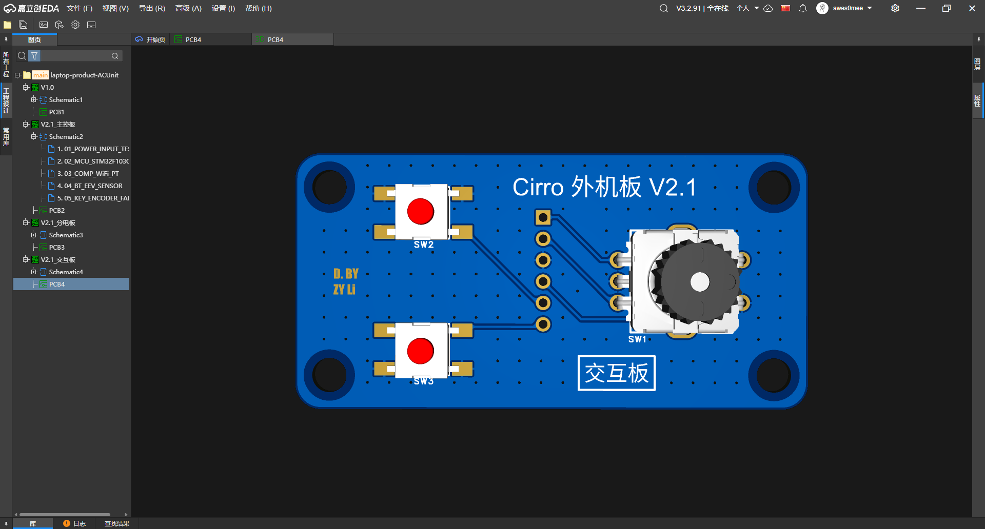
Encoder and two buttons on the interaction board交互板上的编码器与两个按键
The front render reduces the user-input surface to one rotary encoder, two push buttons, six header pads/holes, and four mounting holes.正面渲染把用户输入收在一只旋转编码器、两个按键、六个连接焊盘 / 孔与四个安装孔上。
Project source · Cirro thermal hardware项目来源 · 卷云相变散热系统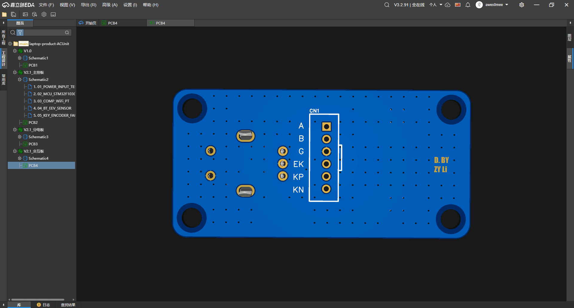 01.08Image图像
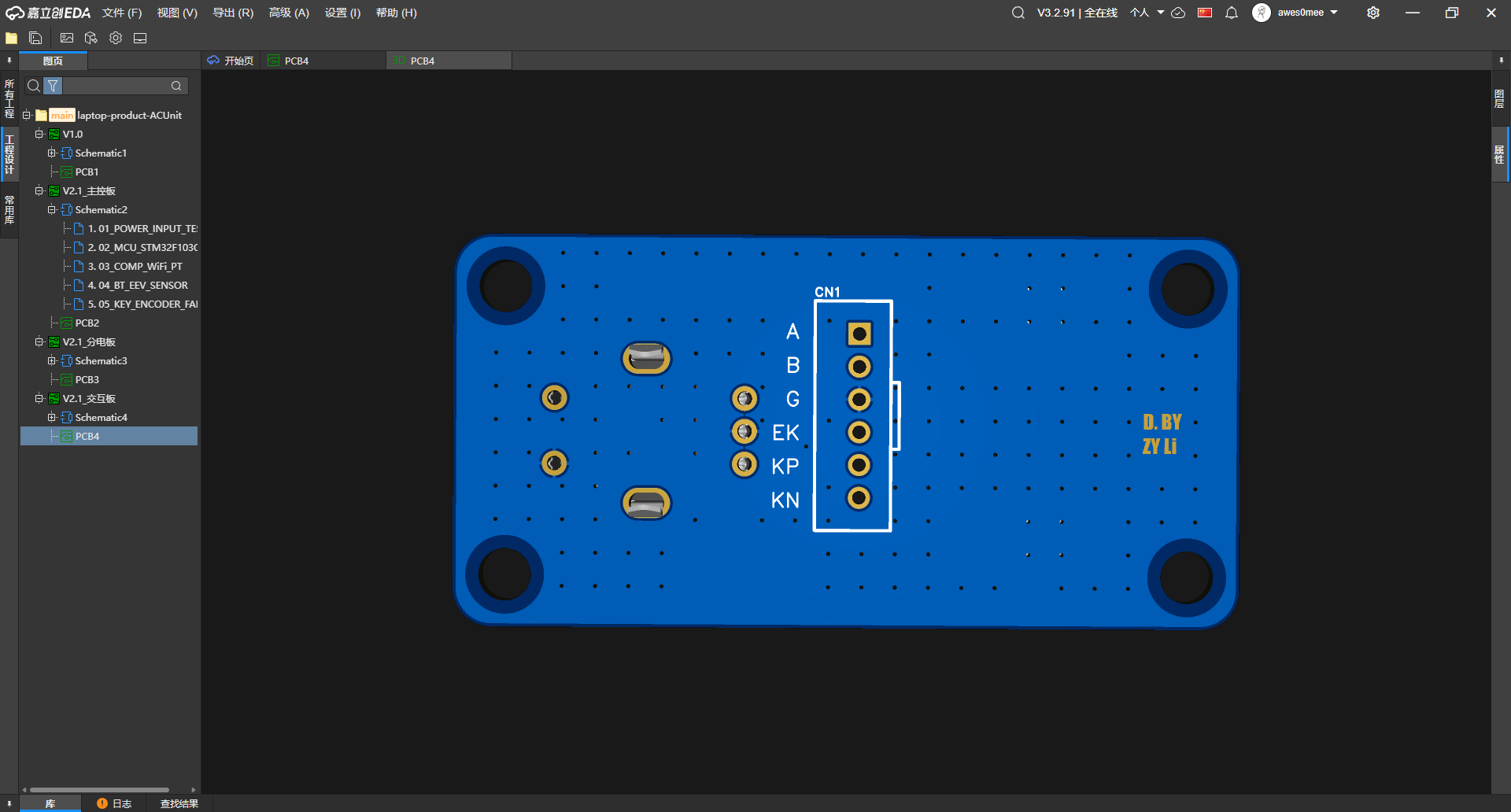
Interaction-header labels from the back从背面读交互板排针标签
The rear view makes the six header labels A, B, G, EK, KP, and KN legible beside the encoder and button footprints.背面视角让 A、B、G、EK、KP、KN 六个排针标签与编码器、按键焊盘的对应关系更清楚。
Project source · Cirro thermal hardware项目来源 · 卷云相变散热系统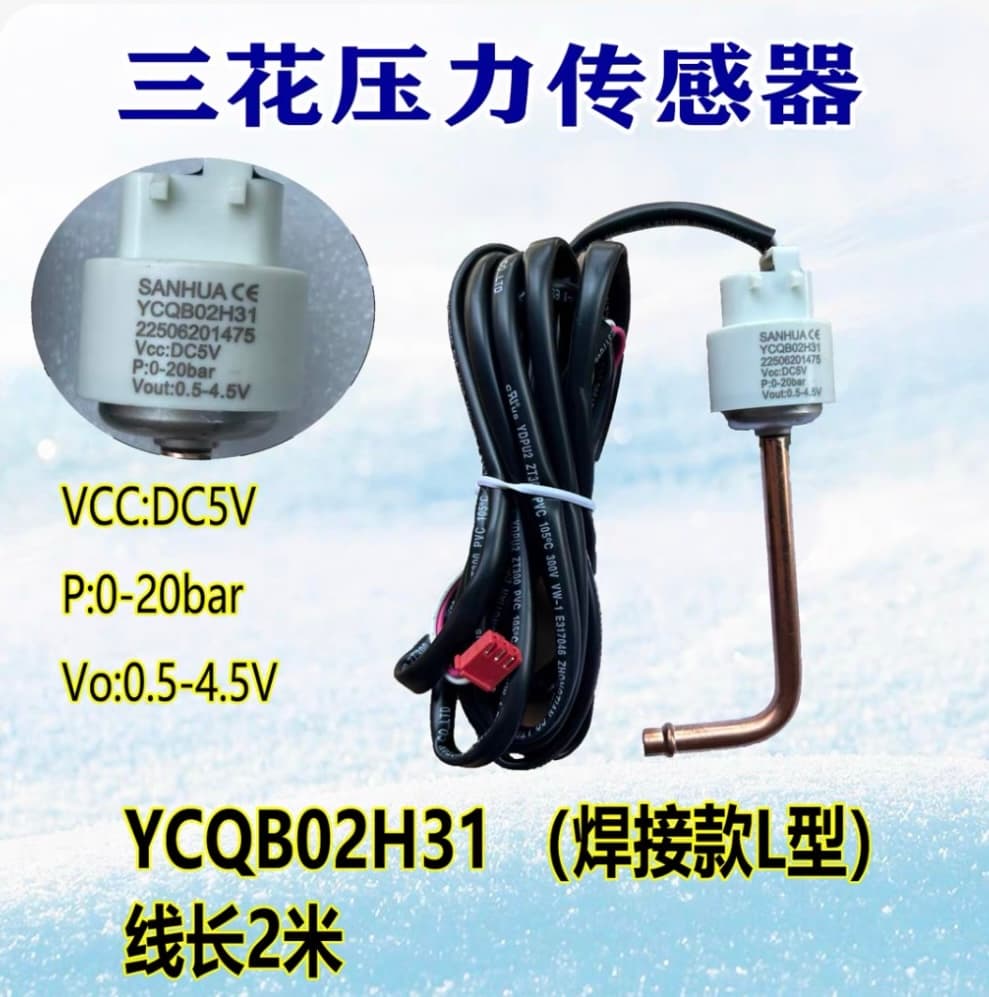 01.09Image图像
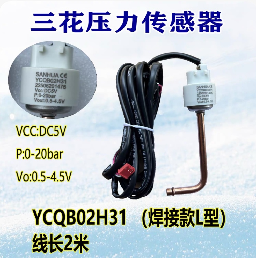
5 V pressure-sensor specification screenshot5 V 压力传感器规格截图
The product image labels a Sanhua YCQB02H31 with 5 V supply, 0-20 bar range, 0.5-4.5 V output, and a two-metre lead; it does not show selection or testing.产品图标注三花 YCQB02H31、5 V 供电、0-20 bar、0.5-4.5 V 输出和两米线长;画面不说明它已经选型或测试。
Project source · Cirro thermal hardware项目来源 · 卷云相变散热系统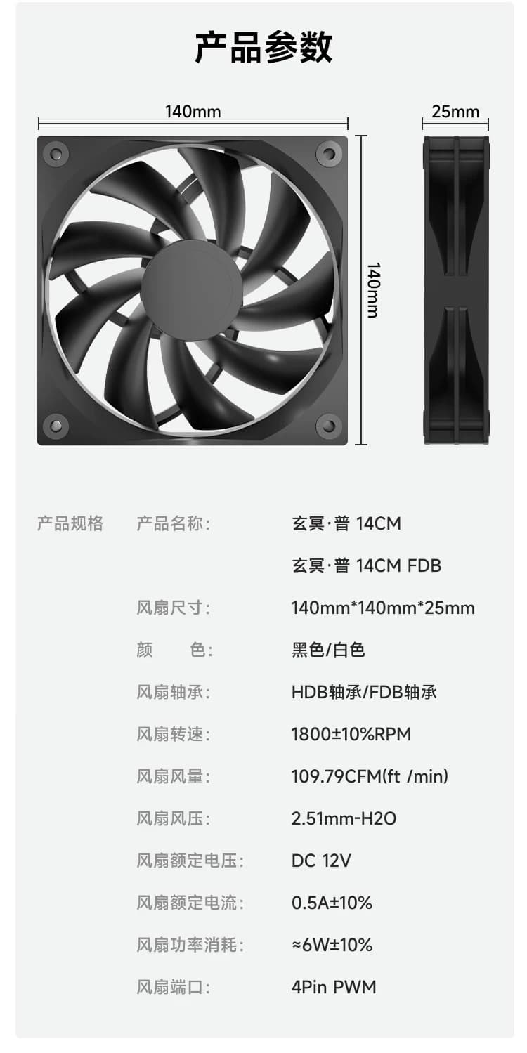 01.10Image图像
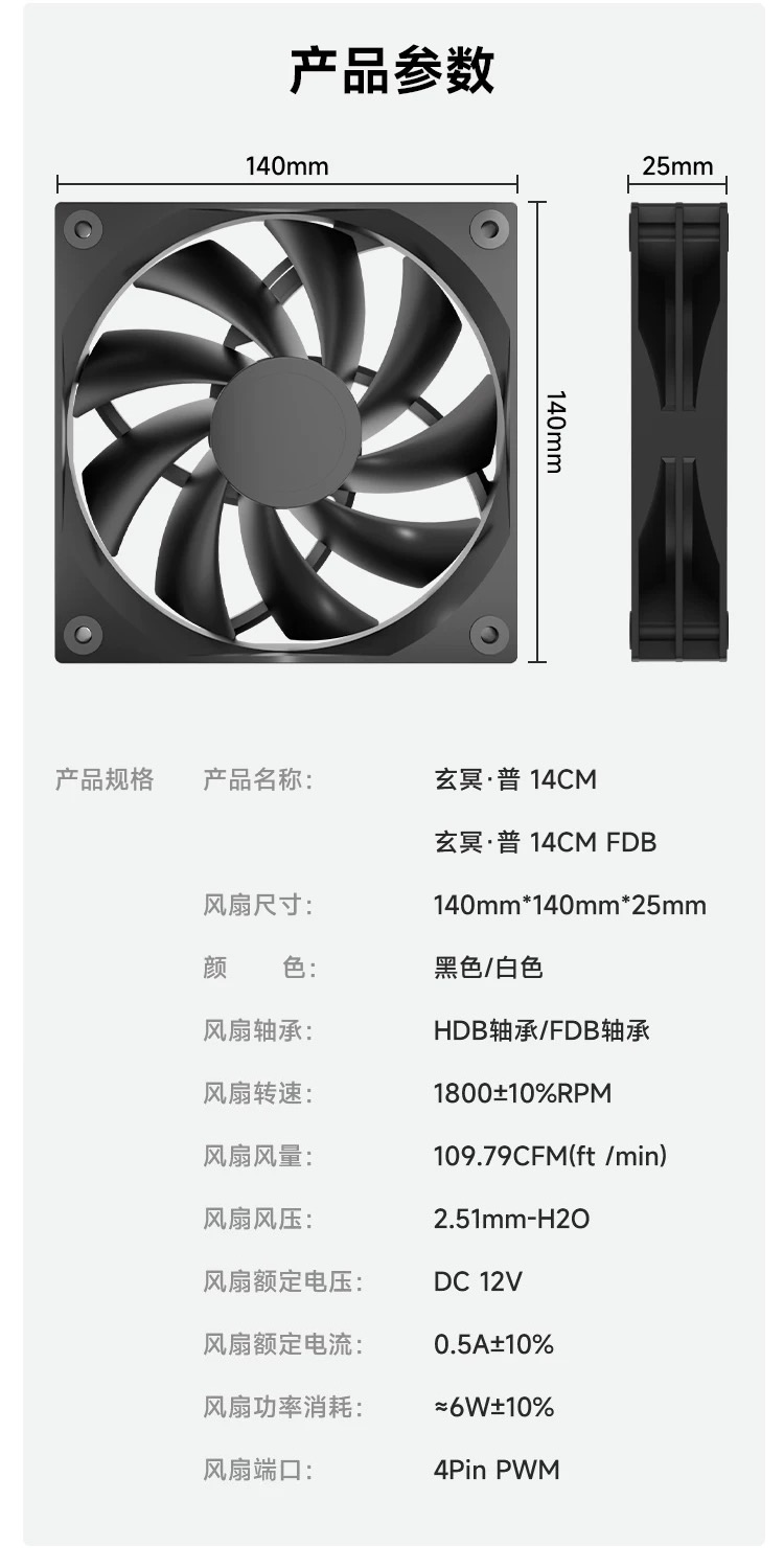
140 mm four-pin PWM fan specification screenshot140 mm 四针 PWM 风扇规格截图
The screenshot lists 140 x 140 x 25 mm, 12 V, 1800+/-10% RPM, and a four-pin PWM connector as candidate interface constraints, not measured platform results.截图列出 140 x 140 x 25 mm、12 V、1800+/-10% RPM 与四针 PWM 接口,可作候选约束,不能当作平台实测结果。
Project source · Cirro thermal hardware项目来源 · 卷云相变散热系统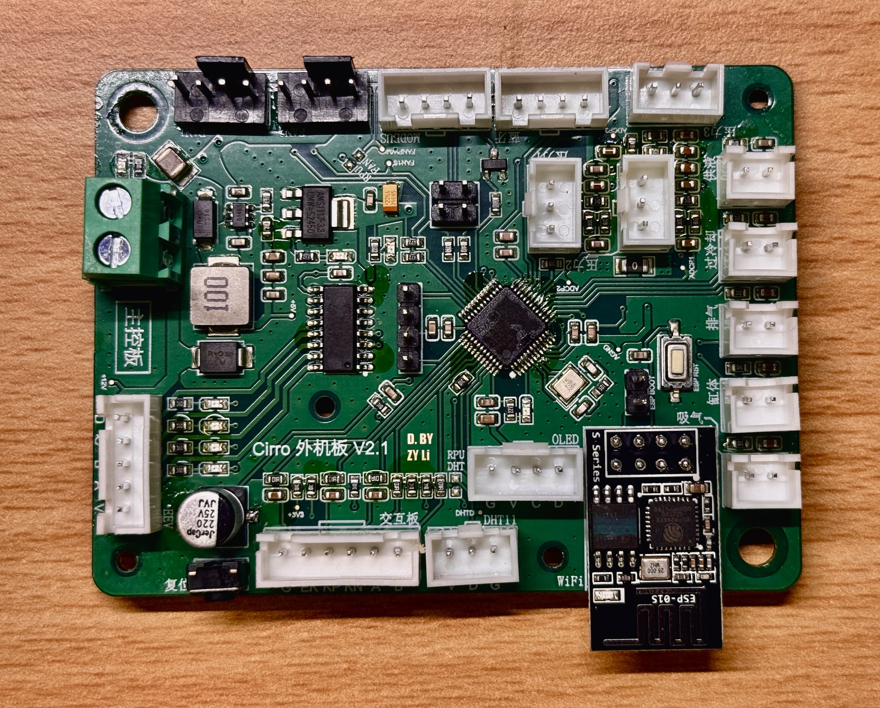 01.11Image图像
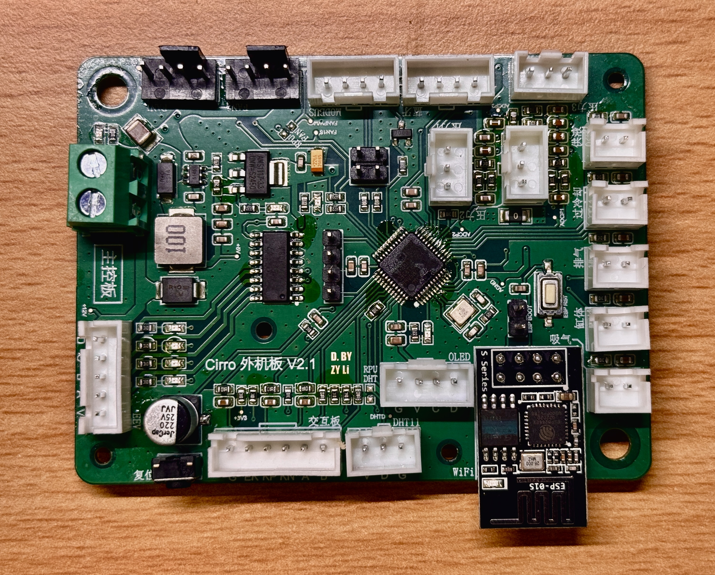
Populated V2.1 ACUnit main board完成装配的 V2.1 ACUnit 主控板
The assembled main board shows the populated STM32, edge connectors, ESP-01S module, and labeled sensor and control headers that had previously appeared only in renders.装配后的主控板实物可见 STM32、板边连接器、ESP-01S 模块,以及此前只出现在渲染图中的传感与控制接口。
Project source · Cirro thermal hardware项目来源 · 卷云相变散热系统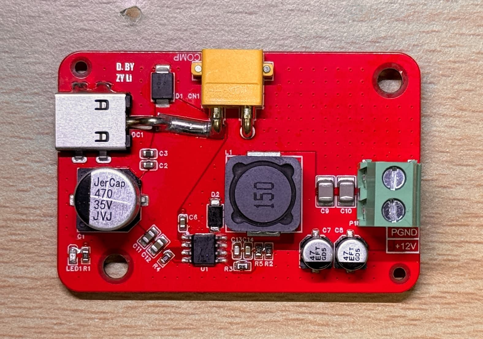 01.12Image图像
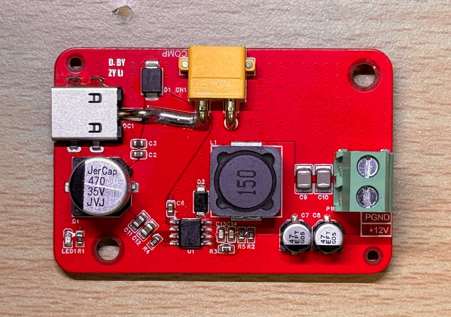
Populated V2.1 ACUnit power board完成装配的 V2.1 ACUnit 分电板
The populated power board brings the DC input, fuse, conversion stage, terminal block, and board-level indicators into one workbench view.装配后的分电板把 DC 输入、保险丝、变换电路、接线端子和板上指示器件落到了同一张工作台实拍中。
Project source · Cirro thermal hardware项目来源 · 卷云相变散热系统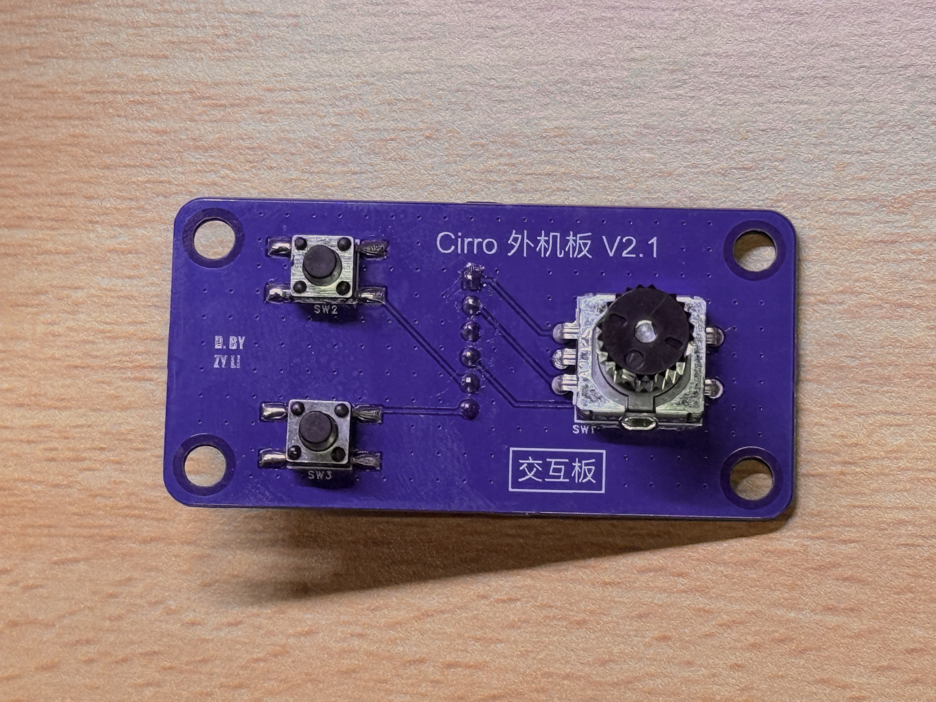 01.13Image图像
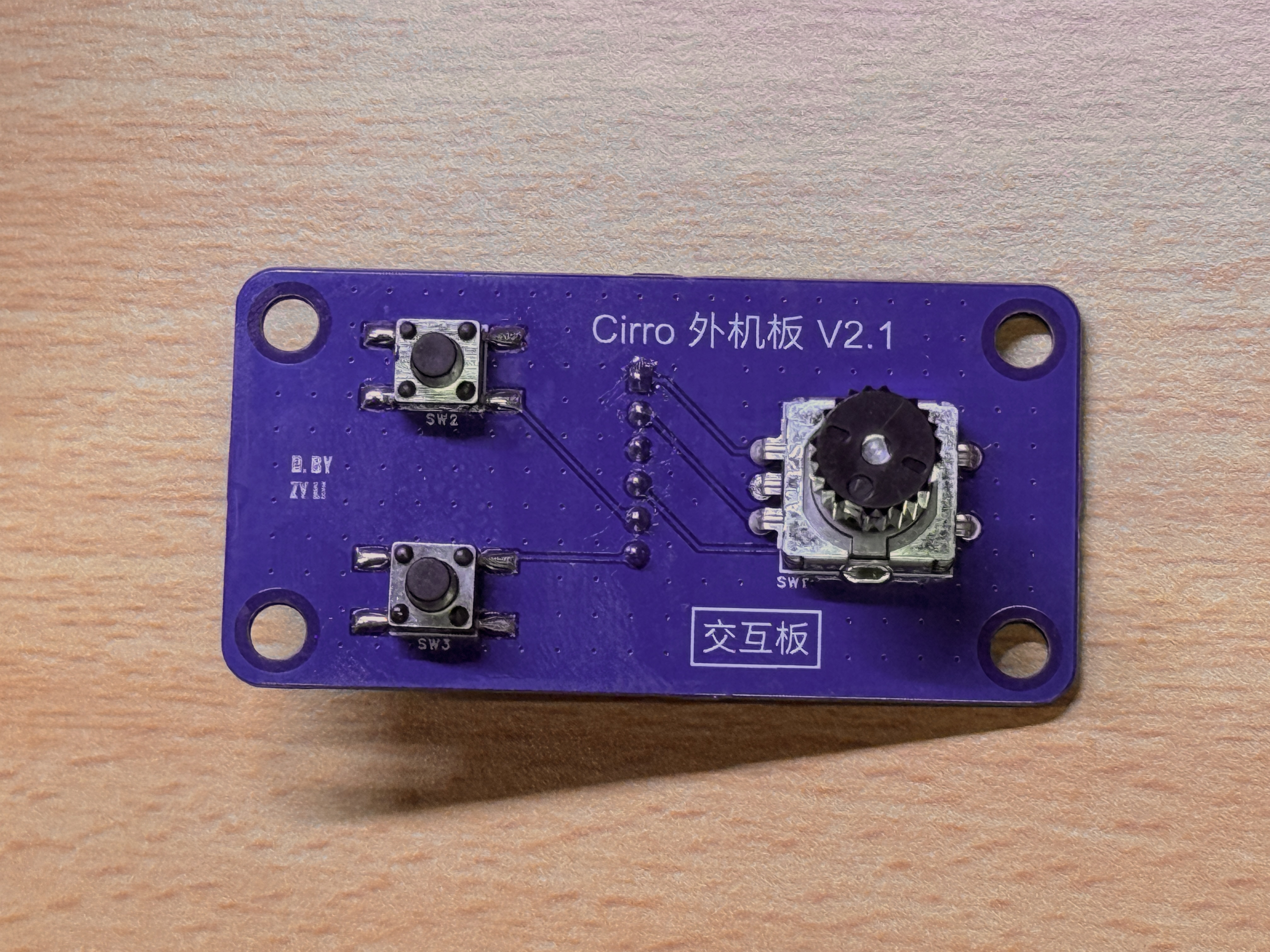
Populated V2.1 ACUnit interaction board完成装配的 V2.1 ACUnit 交互板
The assembled interaction board shows the rotary encoder and two push buttons as soldered hardware rather than PCB-render placeholders.交互板实拍把旋转编码器与两个按键呈现为已经焊接完成的硬件,不再只是 PCB 渲染中的器件位置。
Project source · Cirro thermal hardware项目来源 · 卷云相变散热系统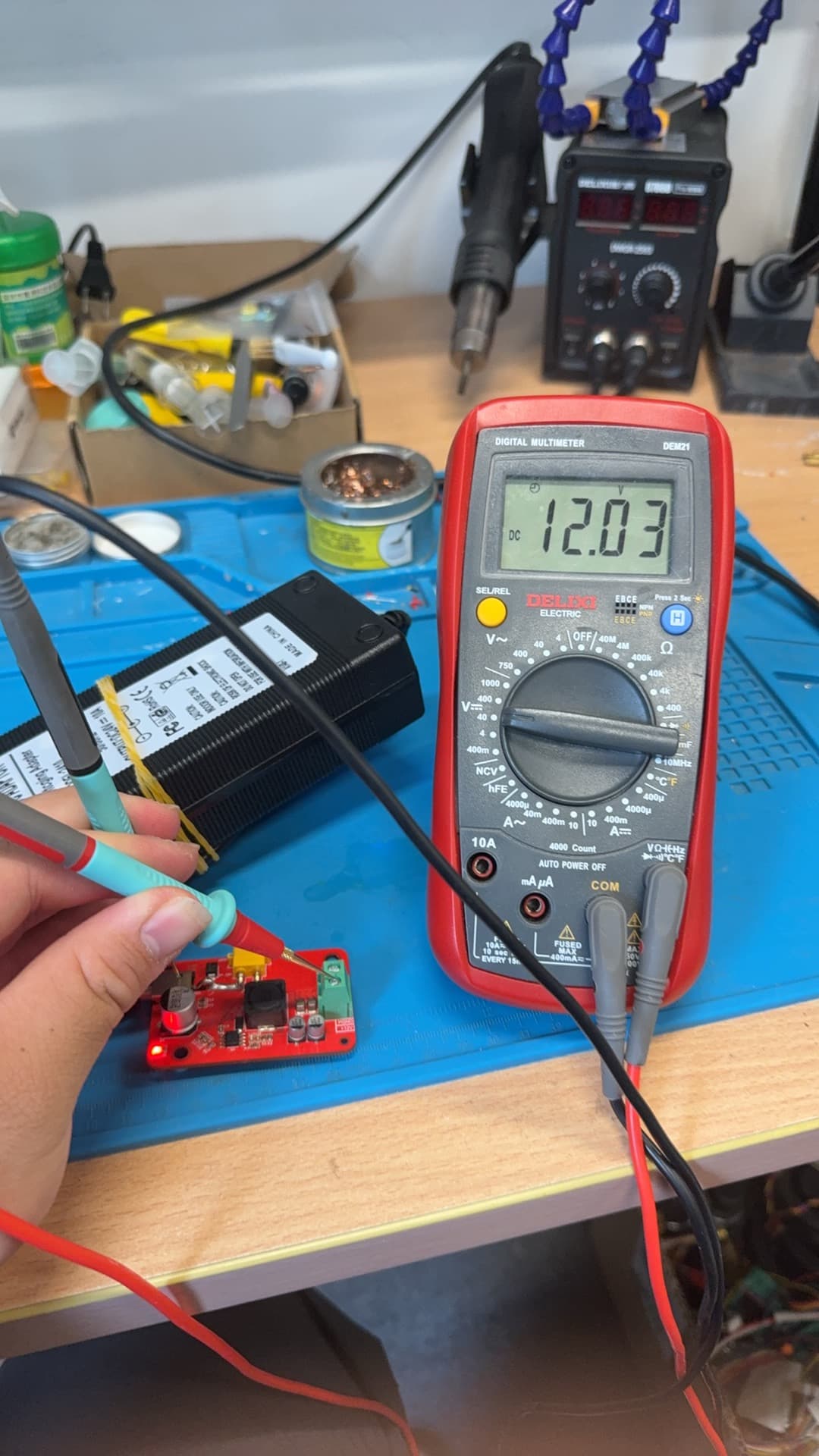 01.14Image图像
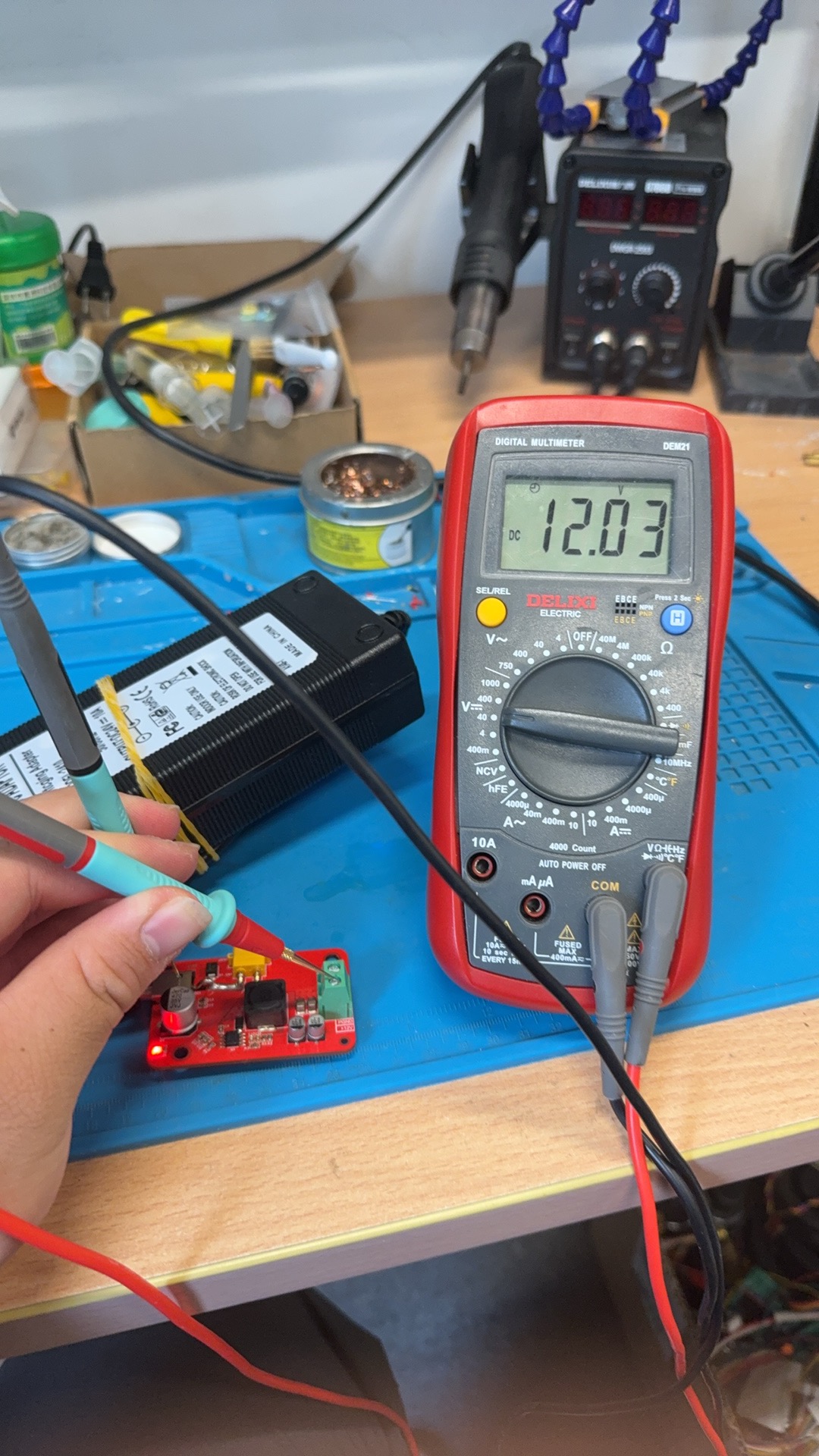
12 V reading during power-board bring-up分电板上电时的 12 V 测量
With the power board energized on the bench, the multimeter display reads 12.03 V during the recorded output check.分电板在工作台上通电后,万用表在这次输出检查中显示 12.03 V。
Project source · Cirro thermal hardware项目来源 · 卷云相变散热系统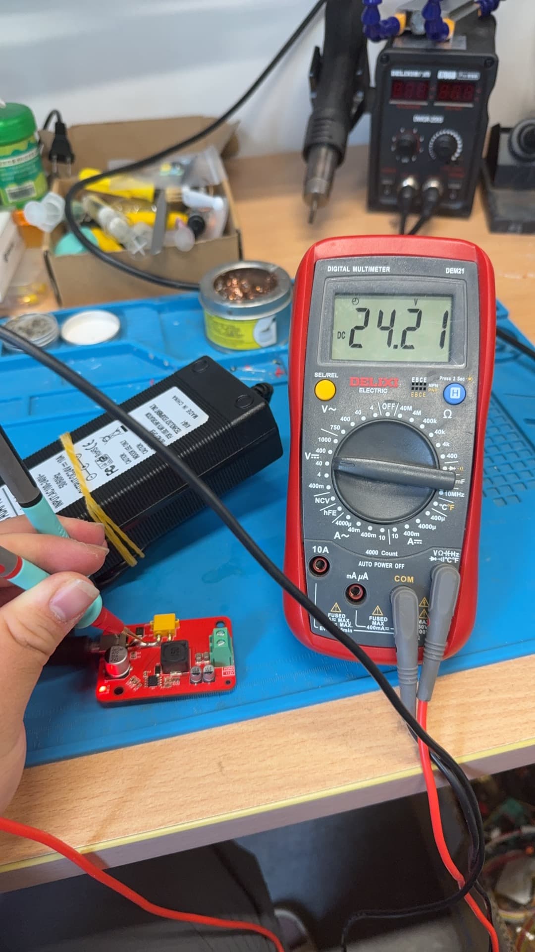 01.15Image图像
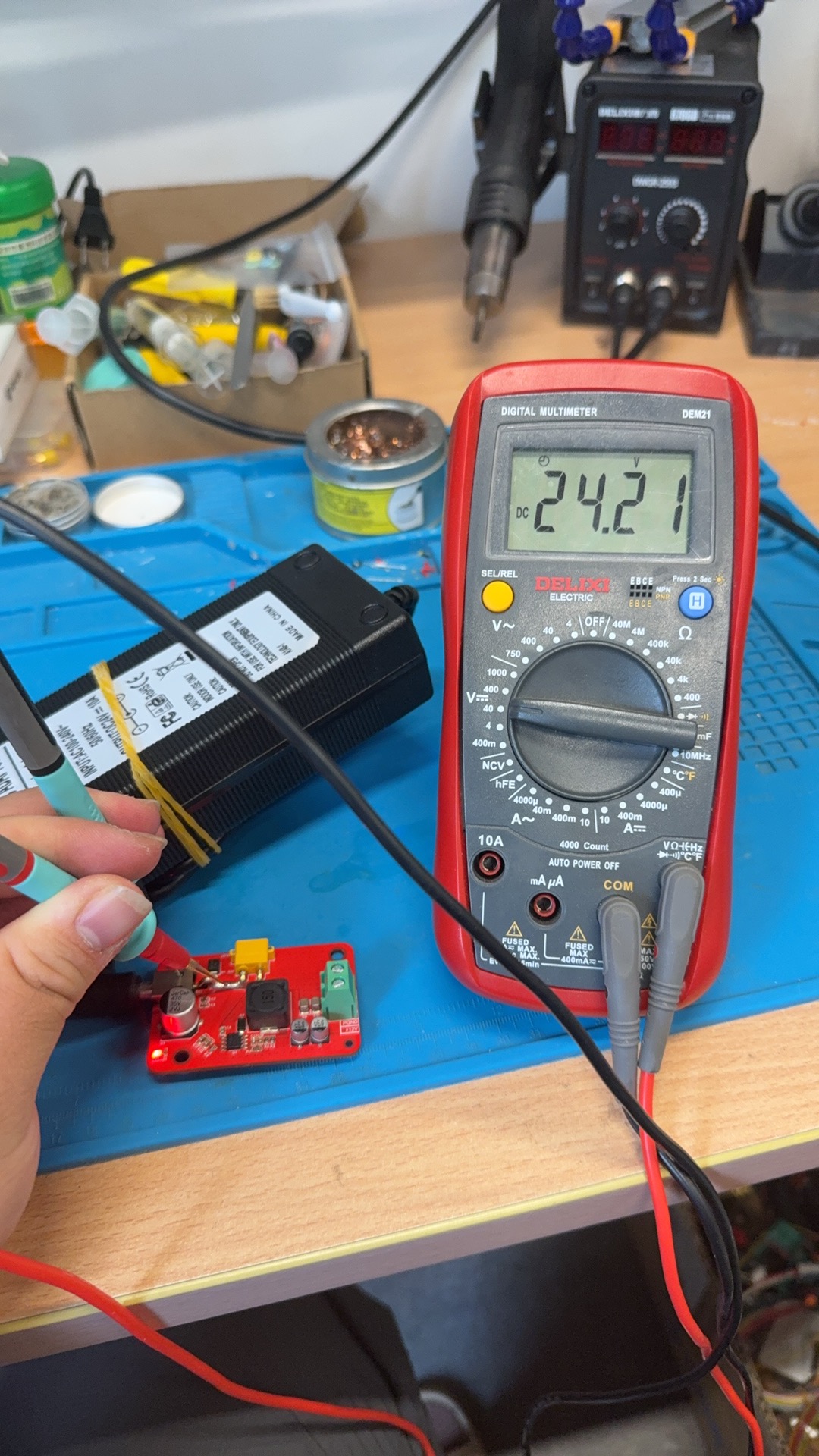
24 V reading during power-board bring-up分电板上电时的 24 V 测量
A second energized-board check records 24.21 V on the multimeter display; the accompanying development record provides the rail context.另一张上电检查照片记录了万用表显示的 24.21 V;具体测量节点由配套开发记录提供语境。
Project source · Cirro thermal hardware项目来源 · 卷云相变散热系统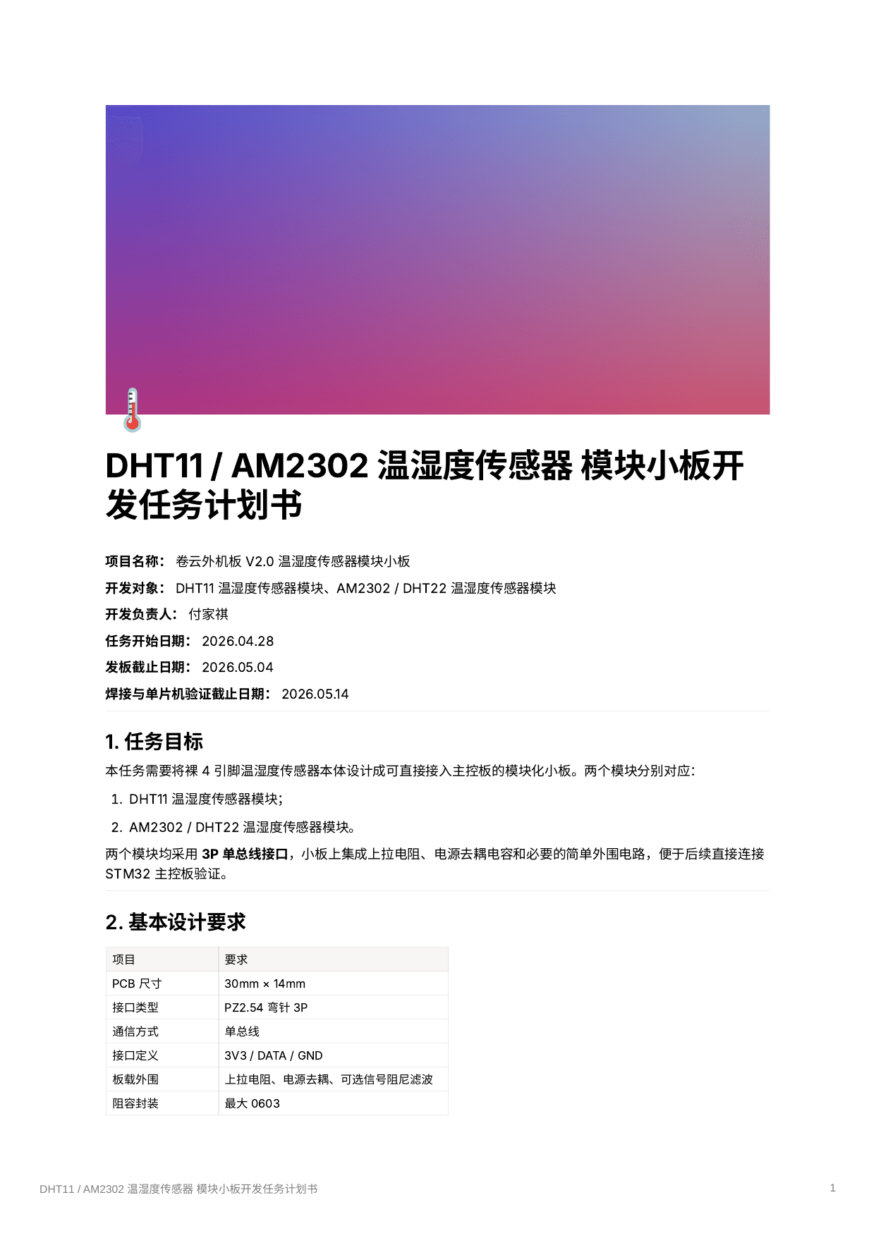 01.16Image图像
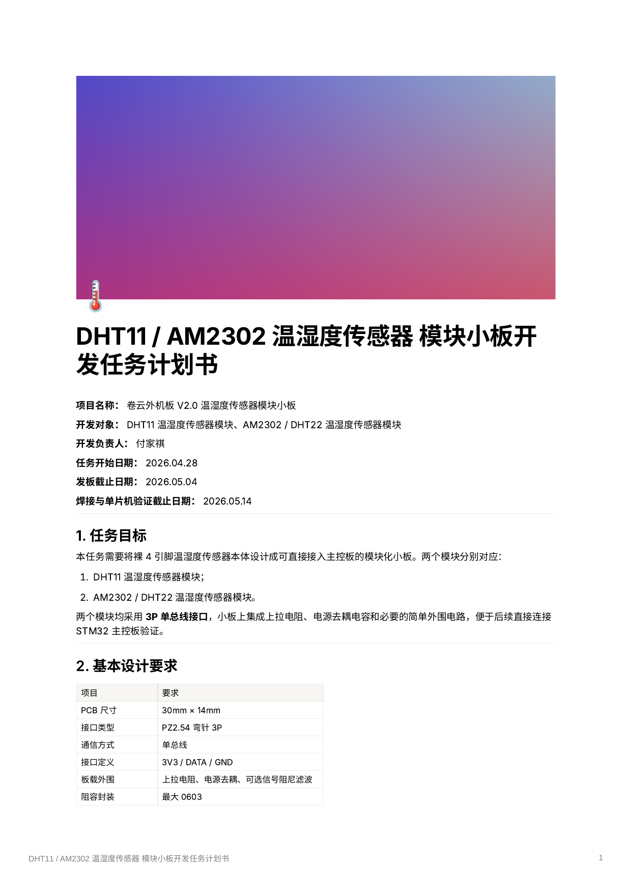
Six-page DHT11 / AM2302 board task plan六页 DHT11 / AM2302 小板任务计划
The cover belongs to an assigned plan for two sensor breakouts, with another development owner named and board, soldering, and MCU checks listed as later milestones in the plan.封面来自两种传感器小板的分配任务,署名另一位开发负责人,并在计划中把发板、焊接与 MCU 检查列为后续节点。
Project source · Cirro thermal hardware项目来源 · 卷云相变散热系统 01.17Image图像
Cover image for the separate hardware SOP独立硬件 SOP 的封面图
This image marks the separate self-authored SOP preserved as its own note and PDF; the cover itself does not summarize the document.这张图指向以独立笔记与 PDF 保留的自写 SOP;单看封面并不能概括文档内容。
Project source · Cirro thermal hardware项目来源 · 卷云相变散热系统 01.18Image图像
Cirro Tech archive cover卷云科技归档封面
A company logo and wordmark used to identify the Juanyun archive context; the mark is not presented as personal design work.用于标识卷云归档语境的公司 Logo 与字标,不把这套标识呈现为个人设计作品。
Project source · Cirro thermal hardware项目来源 · 卷云相变散热系统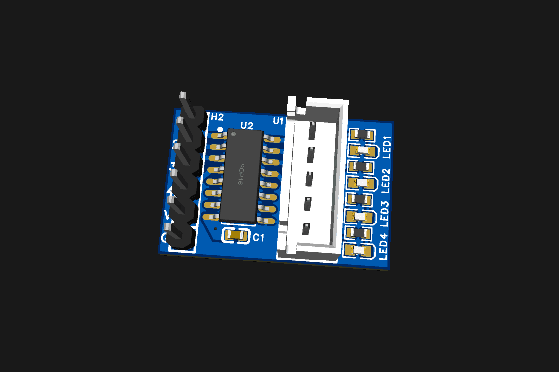 01.19Image图像
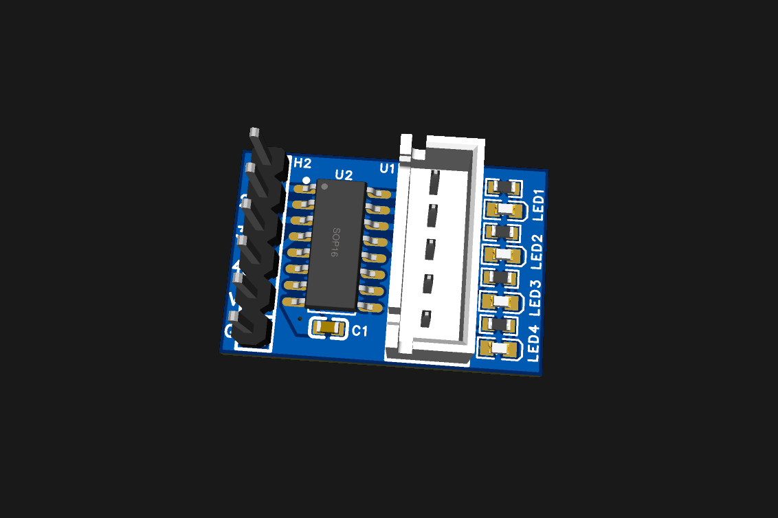
U2 package between the EEV headersEEV 接口之间的 U2 封装
The render shows a four-signal header, an SOP16 U2 package, a five-position output connector, and four LED footprints; the paired schematic identifies U2 as ULN2003A.渲染显示四路信号排针、SOP16 的 U2 封装、五位输出连接器与四个 LED 位置;配套原理图才把 U2 标为 ULN2003A。
Project source · Cirro thermal hardware项目来源 · 卷云相变散热系统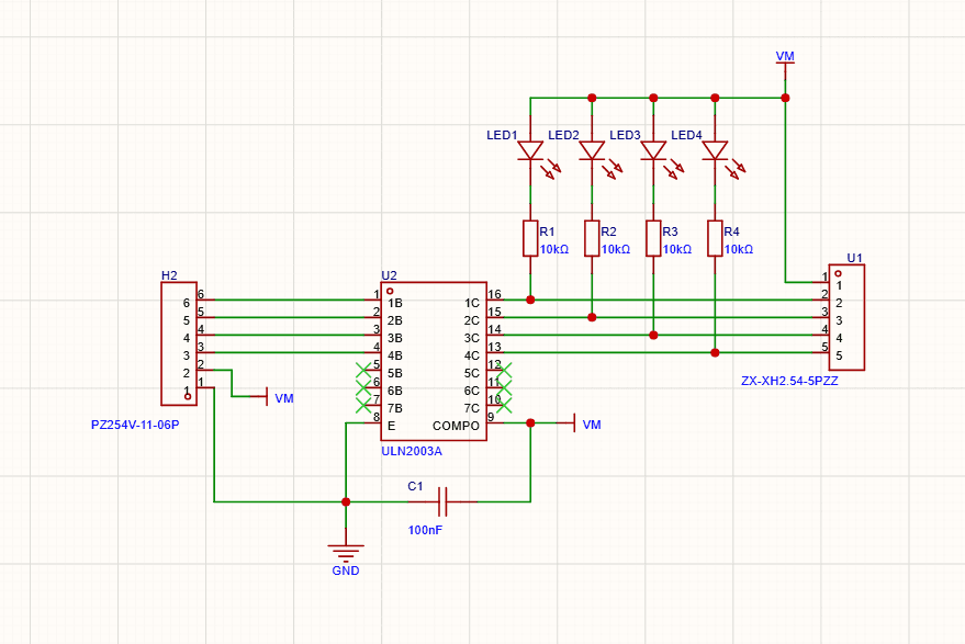 01.20Image图像
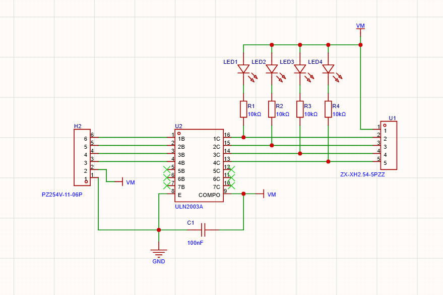
Four EEV channels through a ULN2003A穿过 ULN2003A 的四路 EEV 通道
The schematic routes four inputs through ULN2003A channels to the output connector and attaches an LED-resistor branch to each driven node.原理图让四路输入穿过 ULN2003A 通道到达输出连接器,并在每个驱动节点上接一支 LED 电阻支路。
Project source · Cirro thermal hardware项目来源 · 卷云相变散热系统


Custom Driver Board and Sensorless FOC自制驱动板与无感 FOC 实践
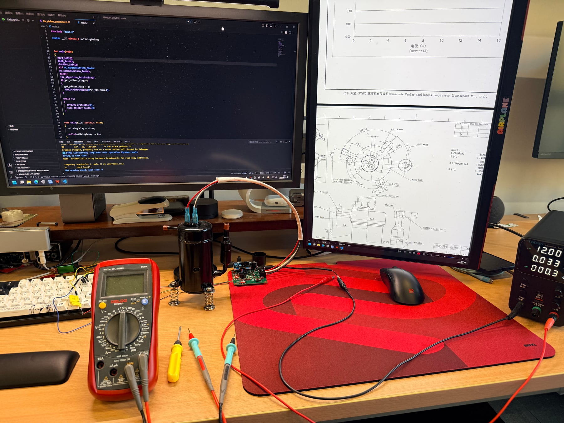
I designed and assembled an STM32F446/DRV8301 driver, adapted open-source firmware, and ran a compressor on a 12 V bus with 30 to 80 Hz open-loop commands. Sensorless handoff remains unresolved.我独立设计、装配 STM32F446/DRV8301 驱动板,适配开源固件,在 12 V 母线下用 30 到 80 Hz 开环指令带动压缩机;无感接管仍未完成。
- Records记录
- 012
- Images图像
- 010
- Videos视频
- 002
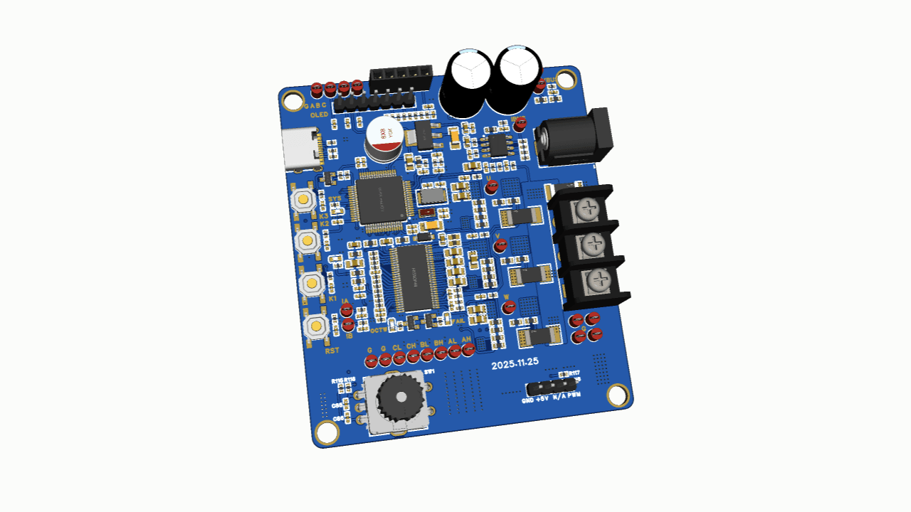 02.01Image图像
Custom FOC Board and Compressor Bench自制 FOC 板与压缩机台架
The cover brings the custom driver board and compressor bench into one frame. It represents the learning route and does not imply a completed sensorless takeover.封面把自制驱动板与压缩机台架放进同一画面。它代表这条学习路线,不表示无感闭环已经完成接管。
Project source · Sensorless FOC项目来源 · 无感 FOC 学习路线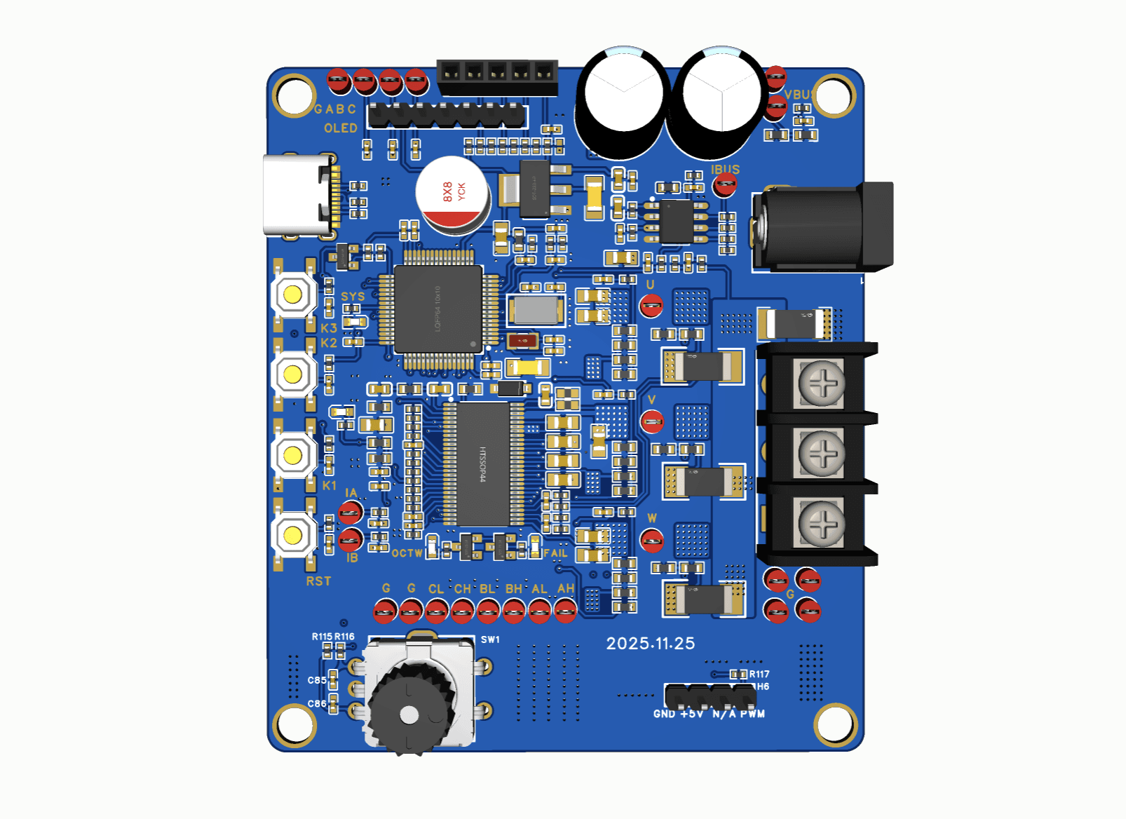 02.02Image图像
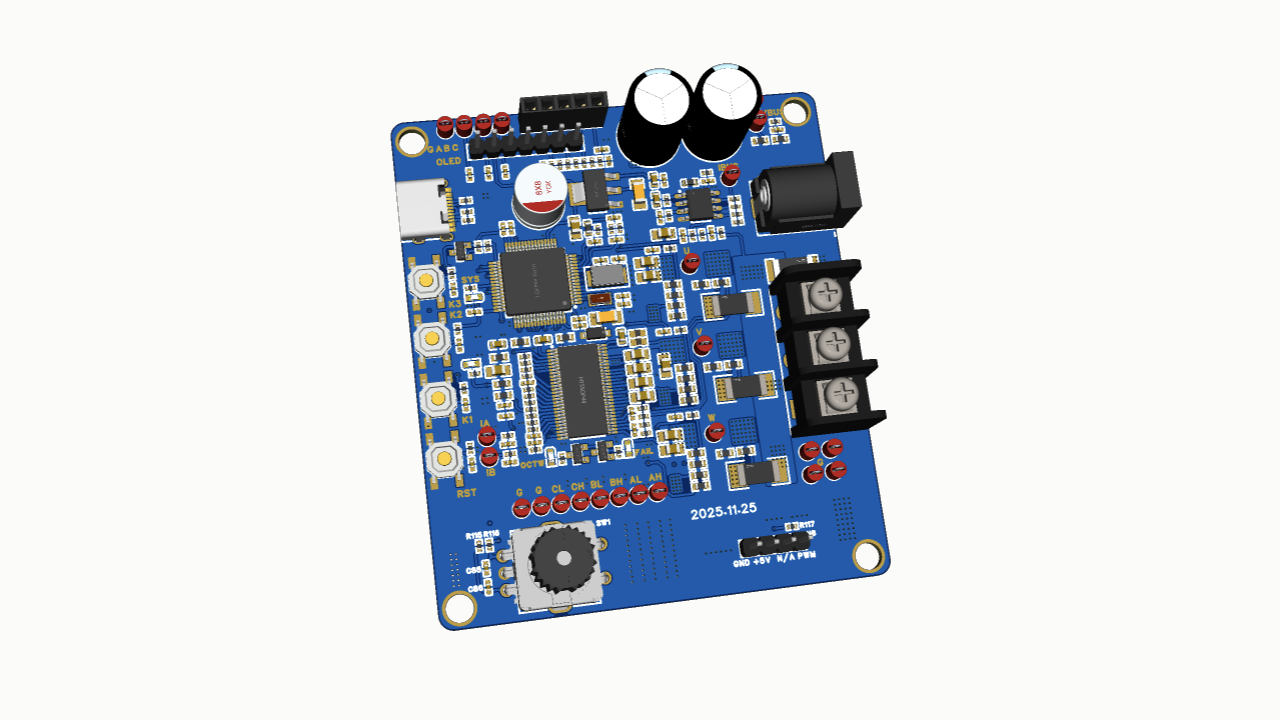
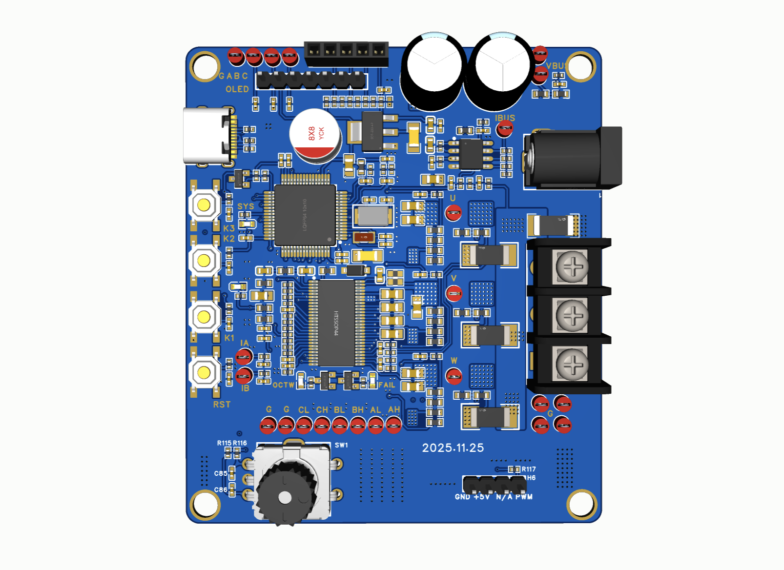
Custom Driver Board Front Render自制驱动板正面渲染
The front render records the STM32F446, DRV8301, six power MOSFETs, controls, and three-phase connector before fabrication. It is layout evidence rather than runtime evidence.正面渲染记录打板前的 STM32F446、DRV8301、六颗功率 MOSFET、交互器件与三相端子。它证明布局内容,不证明运行状态。
Project source · Sensorless FOC项目来源 · 无感 FOC 学习路线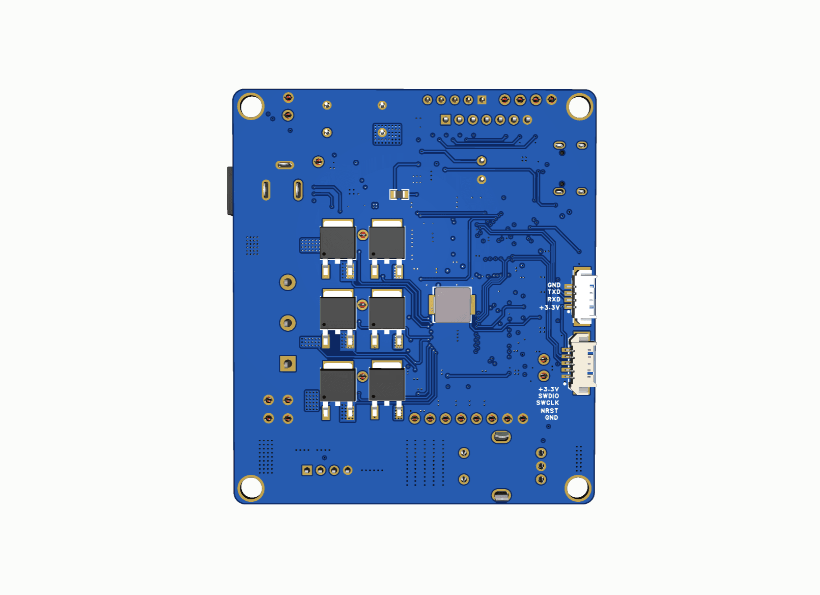 02.03Image图像
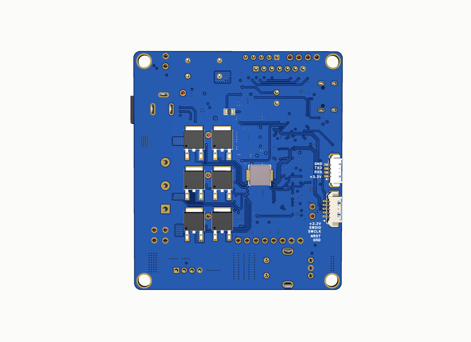
Custom Driver Board Back Render自制驱动板背面渲染
The back render exposes routing and copper distribution on the independently laid out board. It remains design evidence rather than an assembled-board photograph.背面渲染展开我独立 Layout 的走线与铺铜分布。它仍是设计证据,不是装配完成后的实物照片。
Project source · Sensorless FOC项目来源 · 无感 FOC 学习路线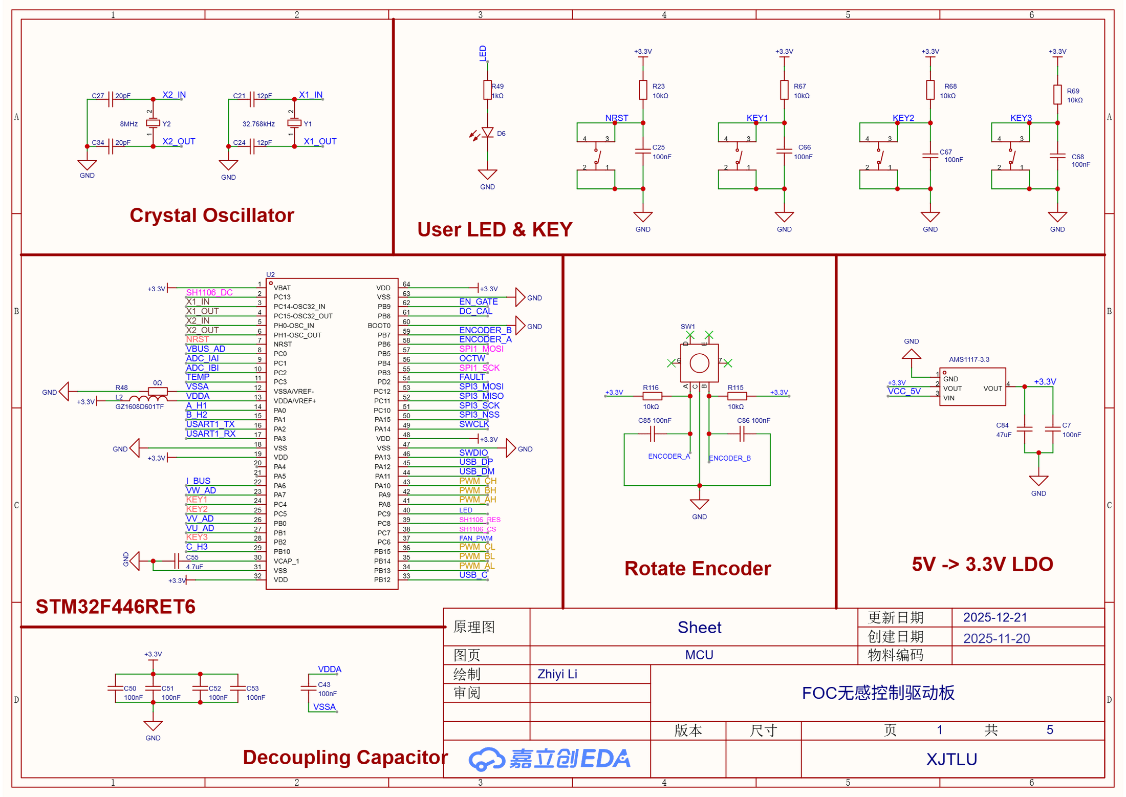 02.04Image图像
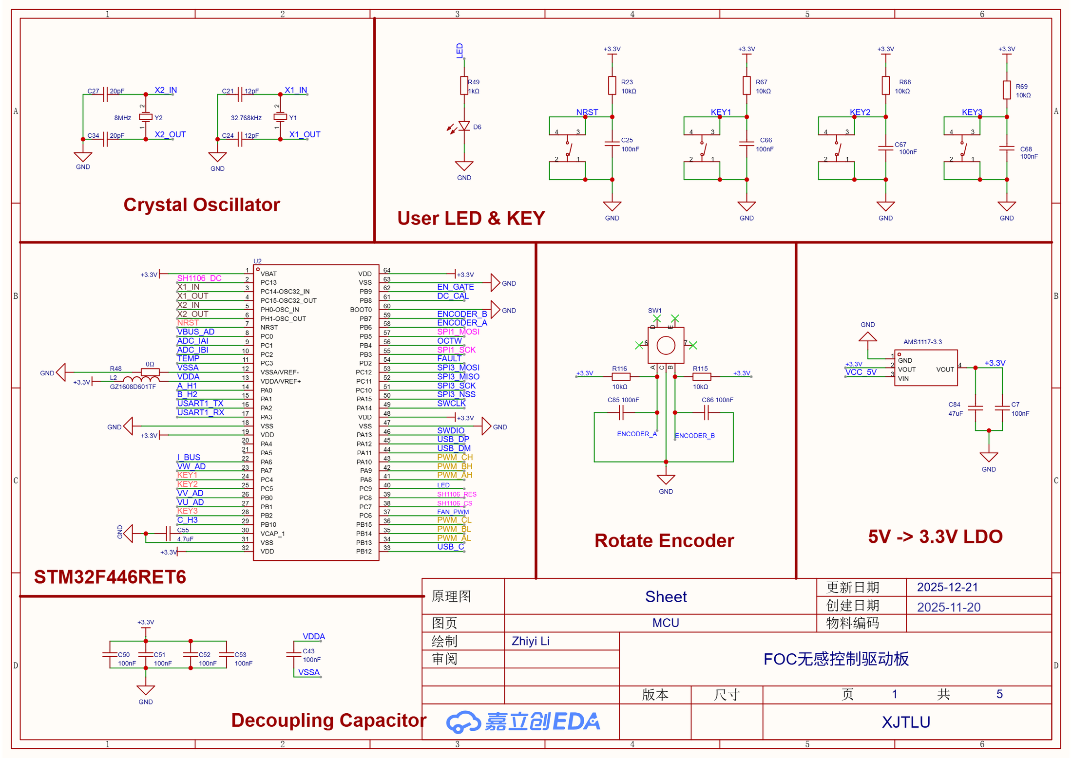
STM32F446 Control and Timing SheetSTM32F446 控制与时序分页
This sheet maps six complementary PWM signals, ADC channels, Hall and encoder interfaces, USB, SWD, SPI, and board controls around the STM32F446RET6.这一页围绕 STM32F446RET6 排布六路互补 PWM、ADC、Hall 与编码器接口、USB、SWD、SPI 和板上交互信号。
Project source · Sensorless FOC项目来源 · 无感 FOC 学习路线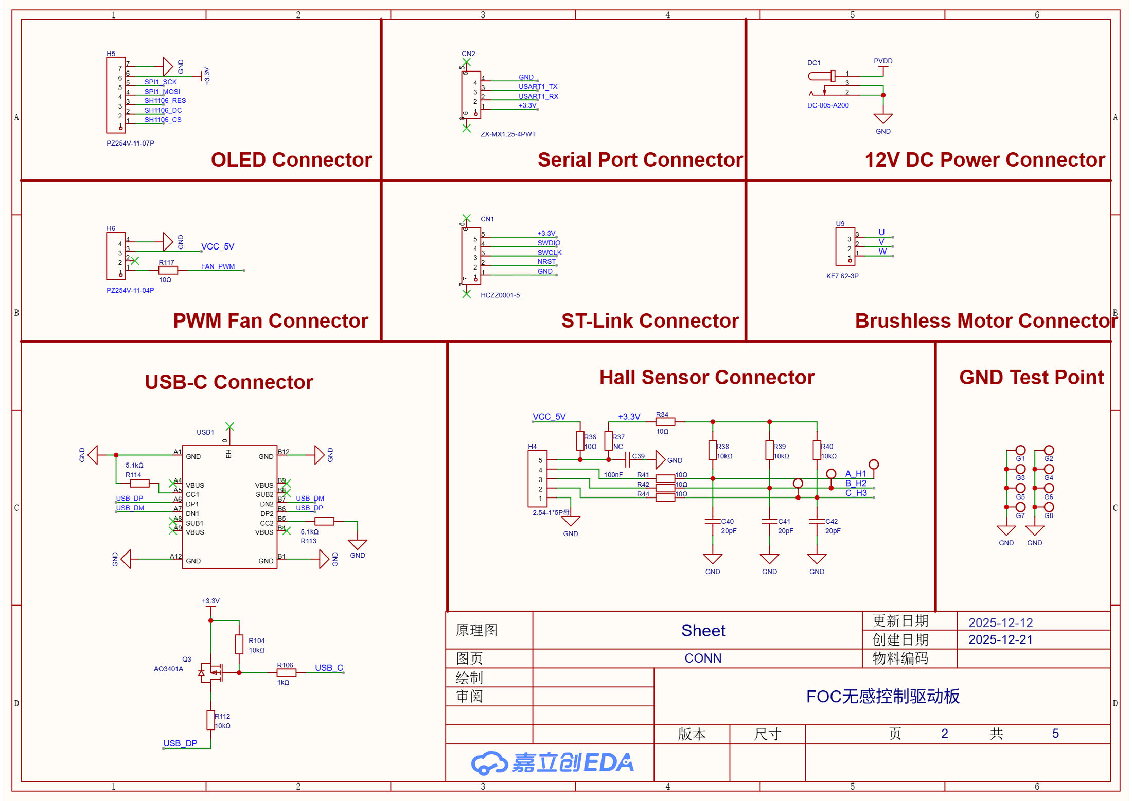 02.05Image图像
Motor Power and Service Connectors电机电源与调试接口分页
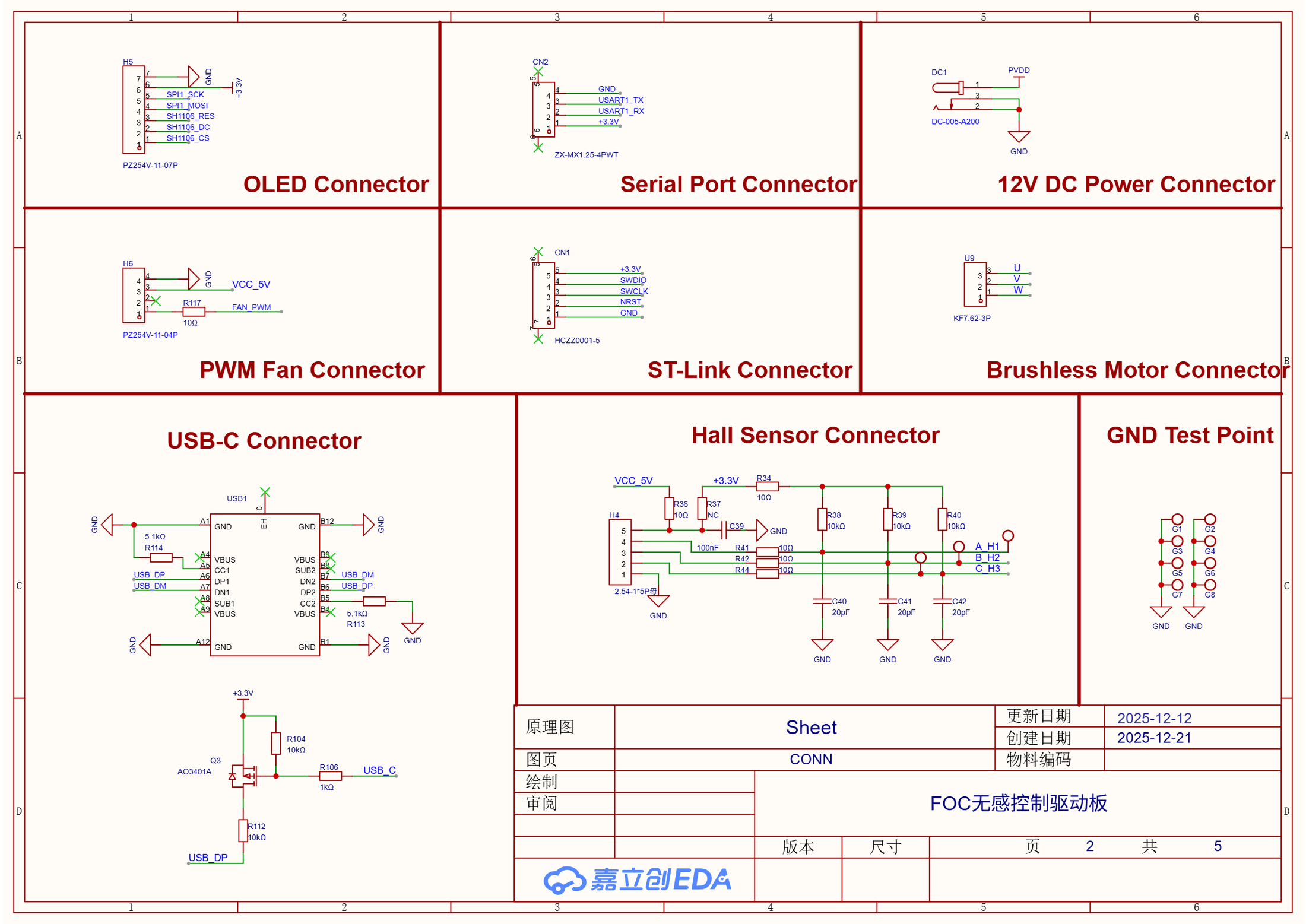
The connector sheet routes U/V/W, Hall inputs, 12 V power, OLED, serial, fan PWM, ST-Link, and USB-C interfaces to the rest of the board.连接器分页把 U/V/W、Hall 输入、12 V 电源、OLED、串口、风扇 PWM、ST-Link 与 USB-C 接到其余电路。
Project source · Sensorless FOC项目来源 · 无感 FOC 学习路线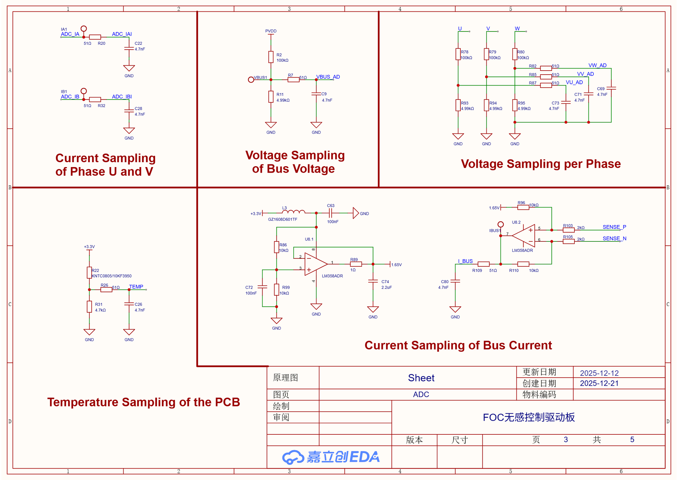 02.06Image图像
Current Voltage and Temperature Sampling电流电压与温度采样分页
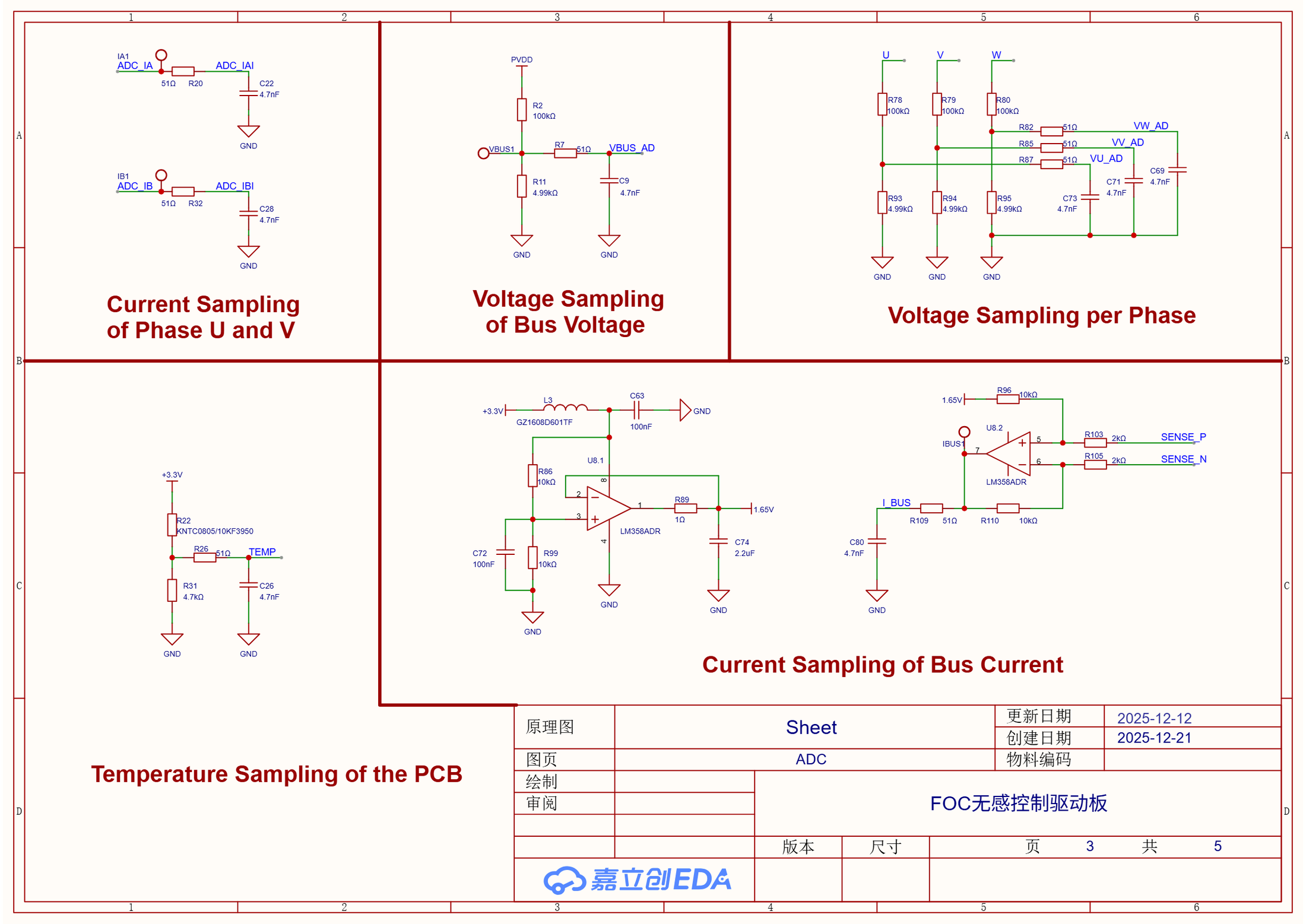
The sampling sheet contains two phase-current channels, bus current and voltage, three phase-voltage dividers, PCB temperature, and the 1.65 V bias path used by the analog front end.采样分页包含两相电流、母线电流与电压、三相电压分压、PCB 温度,以及模拟前端使用的 1.65 V 偏置通路。
Project source · Sensorless FOC项目来源 · 无感 FOC 学习路线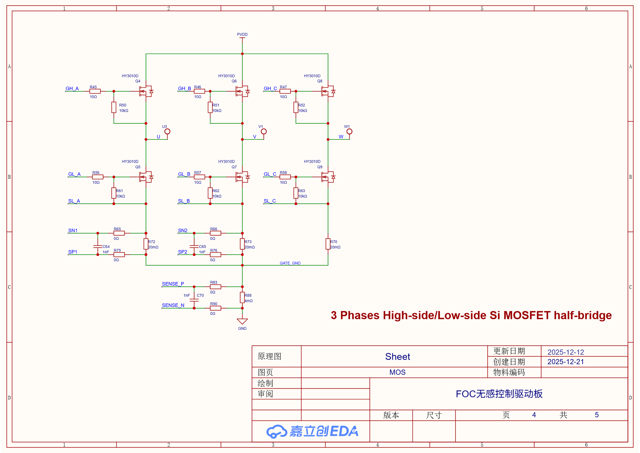 02.07Image图像
HY3010D Three-Phase Power StageHY3010D 三相功率级
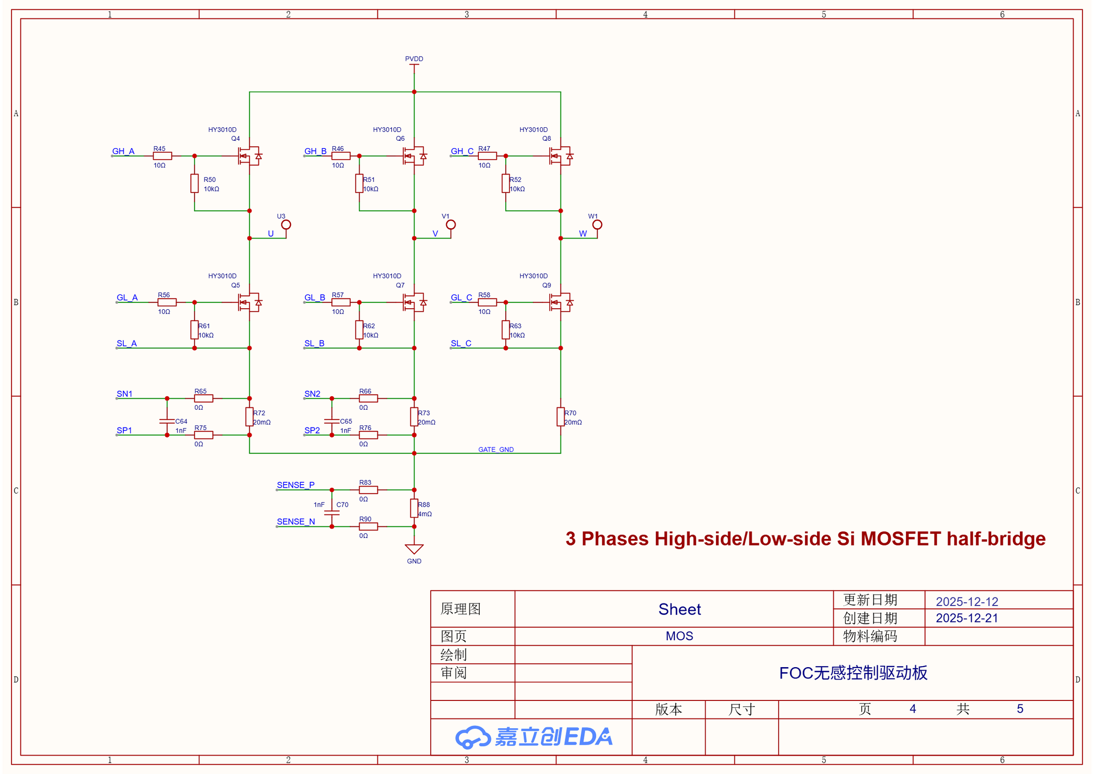
Six HY3010D MOSFETs form the U/V/W half-bridges. The same sheet shows 20 mΩ phase shunts and a 4 mΩ bus shunt used by the current-sensing paths.六颗 HY3010D 组成 U/V/W 三组半桥,同页还能看到采样通路使用的 20 mΩ 相电阻与 4 mΩ 母线电阻。
Project source · Sensorless FOC项目来源 · 无感 FOC 学习路线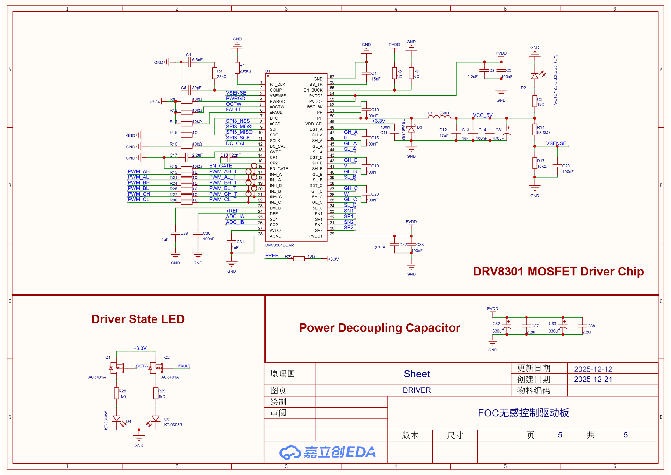 02.08Image图像
DRV8301 Gate Driver and 5 V SupplyDRV8301 栅极驱动与 5 V 电源分页
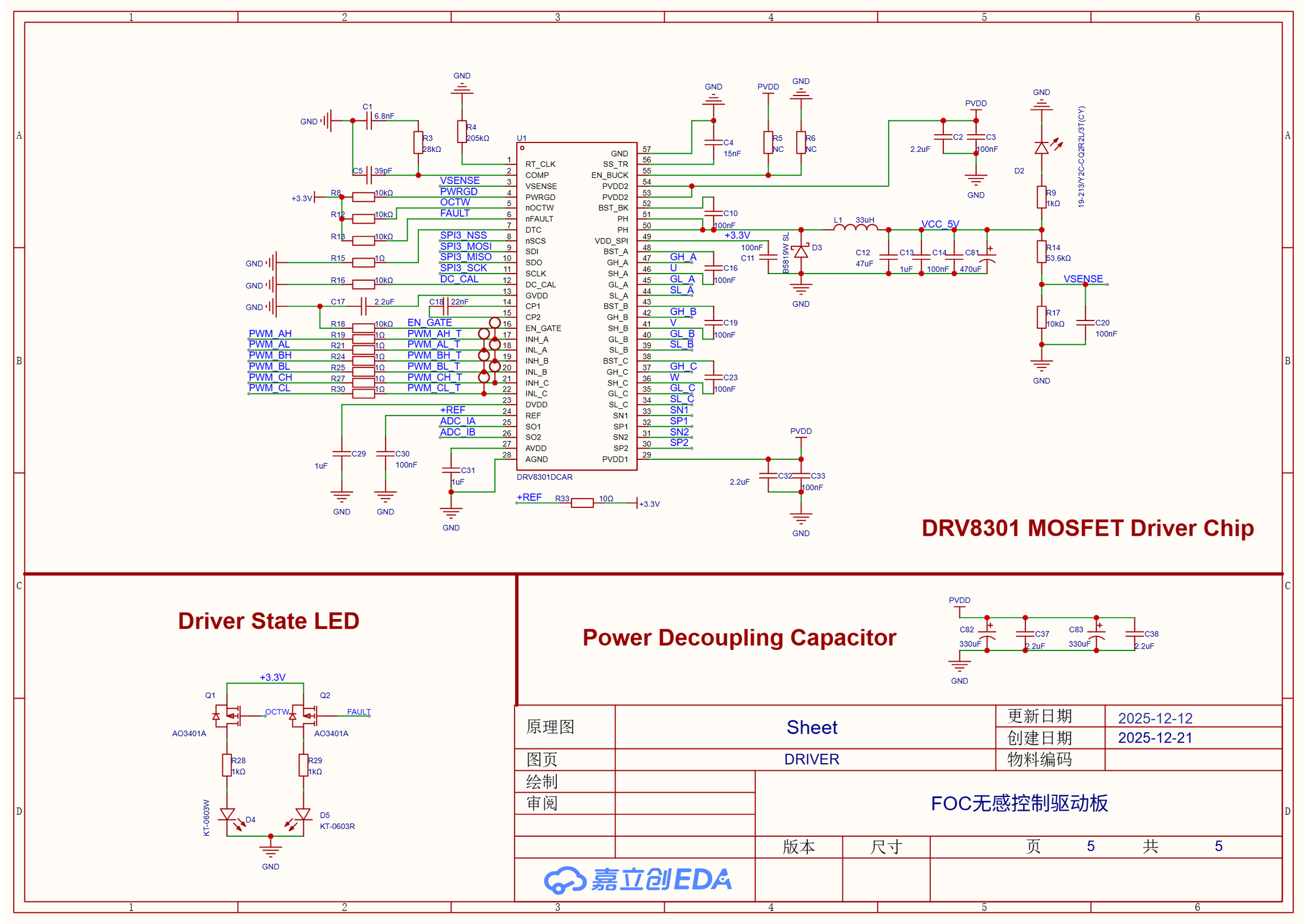
The DRV8301DCAR connects six PWM inputs to three gate pairs and exposes SPI, EN_GATE, nFAULT, OCTW, current-shunt outputs, and the 5 V buck stage.DRV8301DCAR 把六路 PWM 接到三组栅极,并引出 SPI、EN_GATE、nFAULT、OCTW、电流采样放大输出和 5 V 降压级。
Project source · Sensorless FOC项目来源 · 无感 FOC 学习路线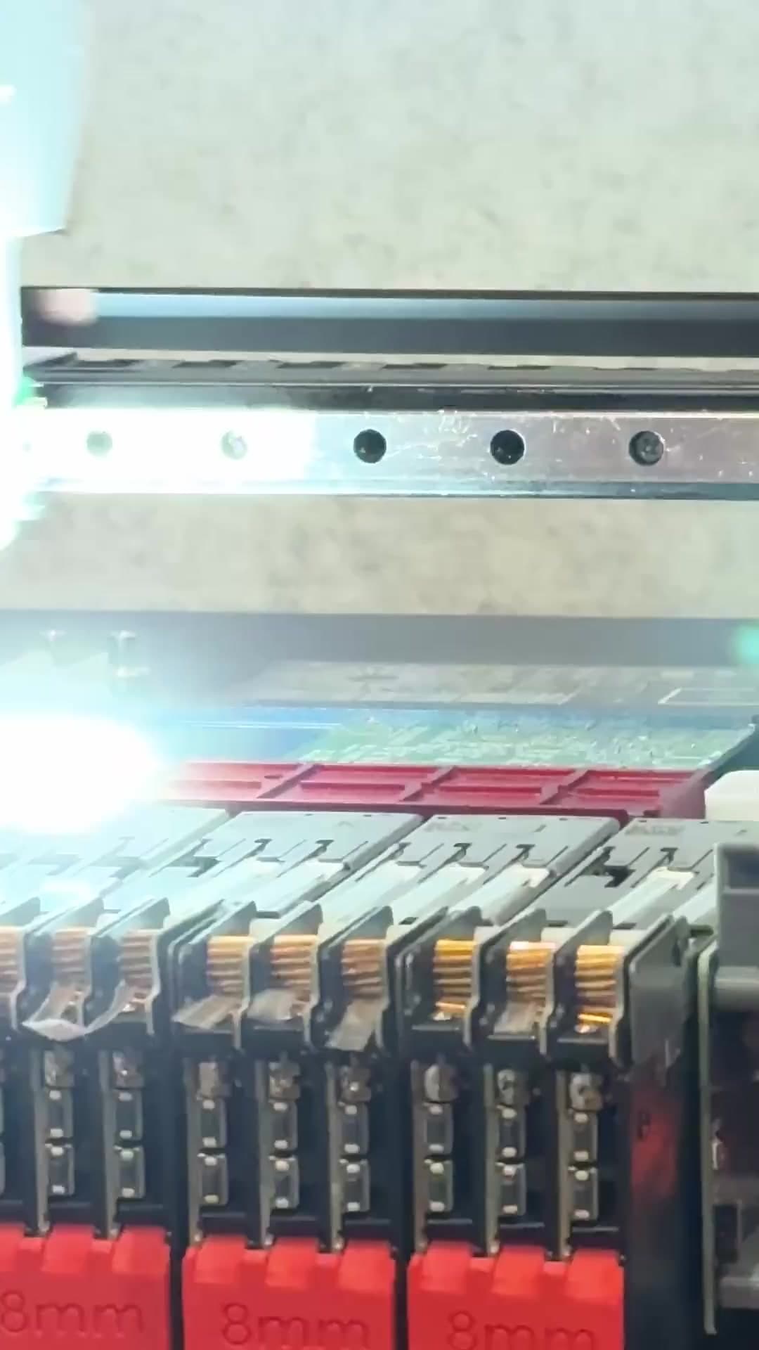 Video视频02.09Video视频
Onsite SMT Feeder and Pick-and-Place Setup现场 SMT 上料与贴片机设置
I loaded the feeders and set the pick-and-place coordinates before operating the SMT equipment for this board. The clip records that manufacturing step.我先完成上料与贴片坐标设置,再操作 SMT 设备生产这块板。视频记录的正是这一段制造过程。
Project source · Sensorless FOC项目来源 · 无感 FOC 学习路线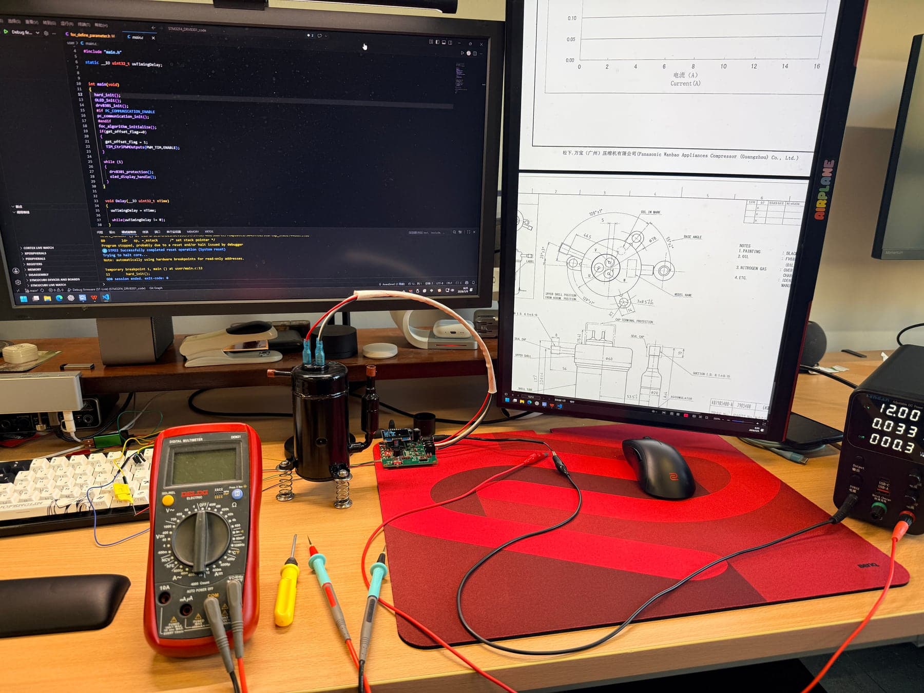 02.10Image图像
Assembled Board and Compressor Bench装配板与压缩机台架
The 12 V bench photograph shows the assembled board, compressor, supply, measurement tools, and live firmware work. It proves the physical setup rather than refrigeration-loop performance.12 V 台架照片同时拍到装配板、压缩机、电源、测量工具与现场固件工作。它证明实物联调,不证明完整制冷回路性能。
Project source · Sensorless FOC项目来源 · 无感 FOC 学习路线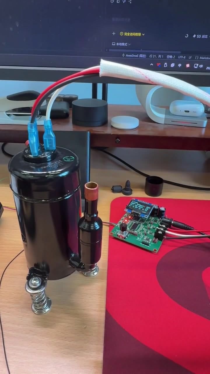 Video视频02.11Video视频
Final Low-Speed EC11 Open-Loop Demo最终低速 EC11 开环演示
The final 30-80 Hz EC11 version records 12 V open-loop operation with both compressor ports open. Manual inlet restriction later in the clip is a disturbance observation rather than pressure or flow validation.最终 30-80 Hz EC11 版本记录 12 V 开环运行,压缩机吸排气口均保持开放。后段人工限制吸气口只是一项扰动观察,不是压力或流量验证。
Project source · Sensorless FOC项目来源 · 无感 FOC 学习路线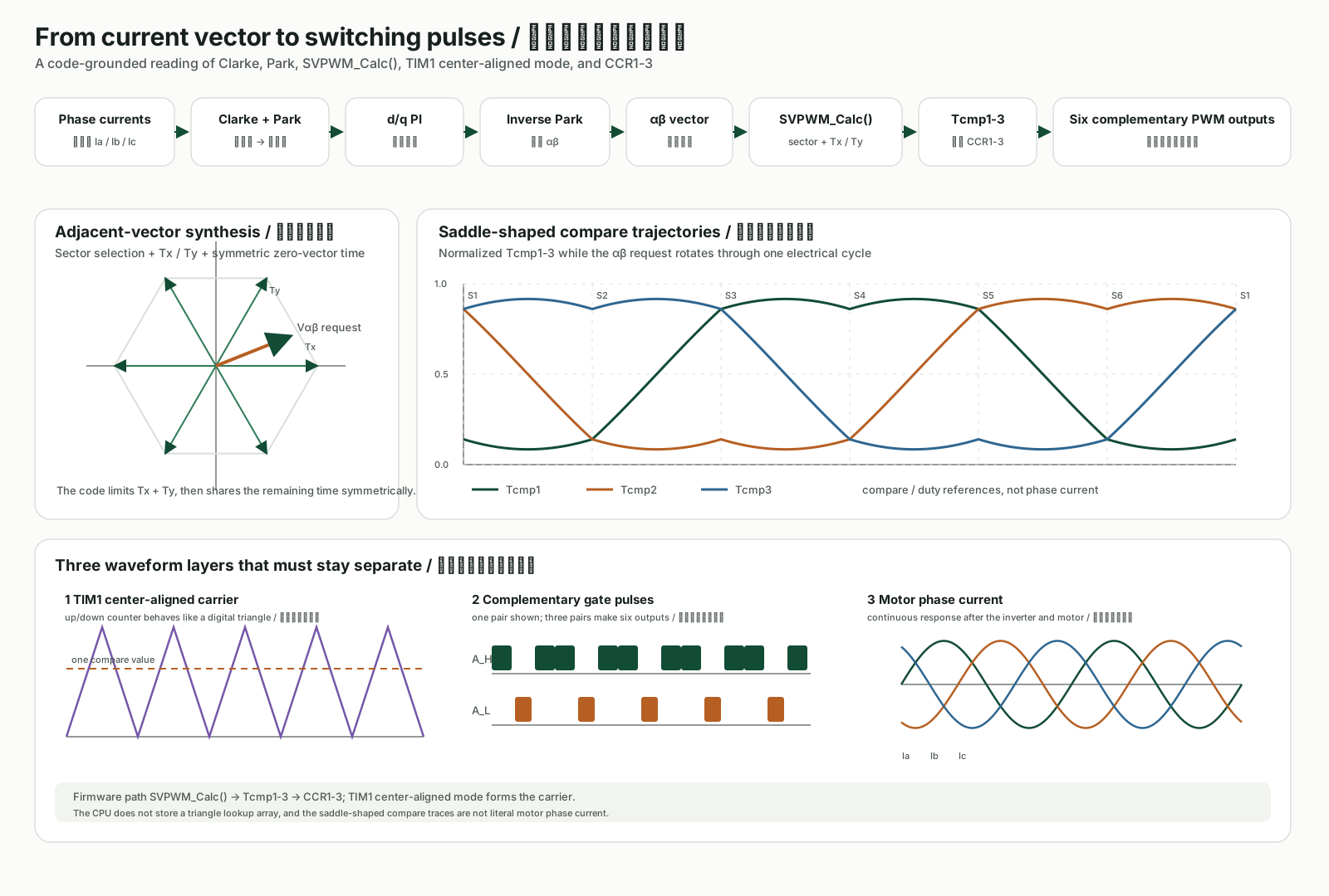 02.12Image图像
FOC and SVPWM Signal ChainFOC 与 SVPWM 信号链
This original diagram reconstructs the firmware path from Clarke and Park transforms through dq current control to SVPWM compare values, center-aligned PWM, gate pulses, and phase current.这张原创图依照固件重建从 Clarke、Park 与 dq 电流控制到 SVPWM 比较值、中心对齐 PWM、栅极脉冲和相电流的路径。
Project source · Sensorless FOC项目来源 · 无感 FOC 学习路线
DIY Laptop CoolerDIY 压风式笔记本散热器
I built an acrylic-and-foam laptop cooler, with a Windows application sending temperatures over Bluetooth to an ESP32 fan controller. A later STM32 board reached serial control but never rejoined the complete system.我做了一台亚克力与泡棉散热器,用 Windows 程序读取温度,经蓝牙控制 ESP32 和风扇。后来重画的 STM32 板完成了串口控制,尚未重新接成完整的温控整机。
- Records记录
- 006
- Images图像
- 005
- Videos视频
- 001
 Video视频03.01Video视频
One Click Connected Windows Temperature to Fan Duty一次点击,把 Windows 温度接到风扇占空比
The 3 min 57 s recording demonstrates the integrated Windows, Bluetooth SPP, and ESP32 chain. Temperatures appear in the app, duty and mode appear on the OLED, and the fan responds to data and buttons. The recording does not contain synchronized temperature, RPM, or performance logs.这段 3 分 57 秒录像演示了 Windows、Bluetooth SPP 与 ESP32 完整链路。上位机显示温度,OLED 显示占空比与模式,风扇响应数据和按键;录像不包含同步温度、RPM 或性能日志。
Project source · DIY cooling项目来源 · DIY 压风式散热器- 03.02Image图像
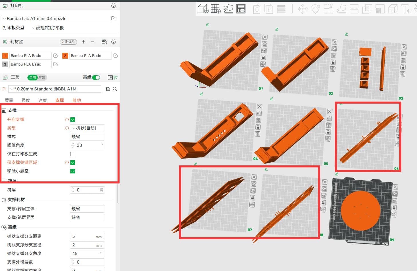
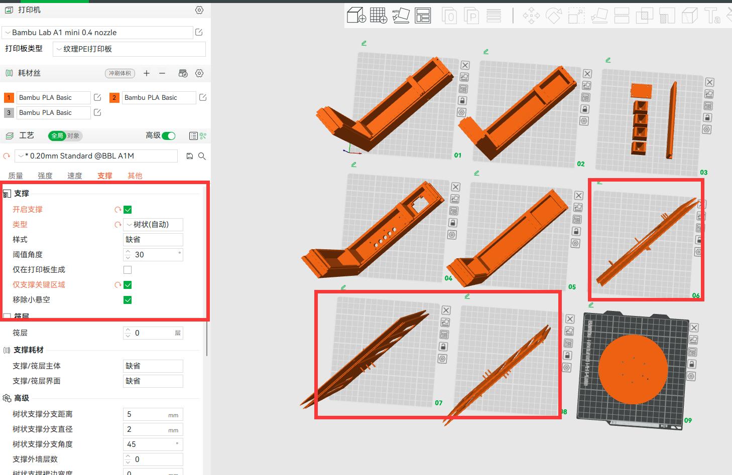
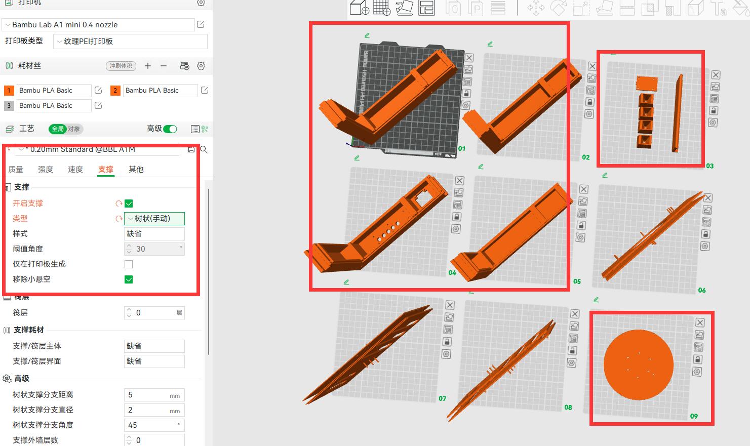
Nine A1 mini Build Plates That Remained Digital停留在数字阶段的九块 A1 mini 切片板
The long enclosure was split across nine A1 mini build plates with automatic tree supports. Modeling and slicing were completed; printing and assembly were not.长外壳被拆分到九块 A1 mini 切片板,并配置自动树状支撑;建模与切片完成,打印和装配没有进行。
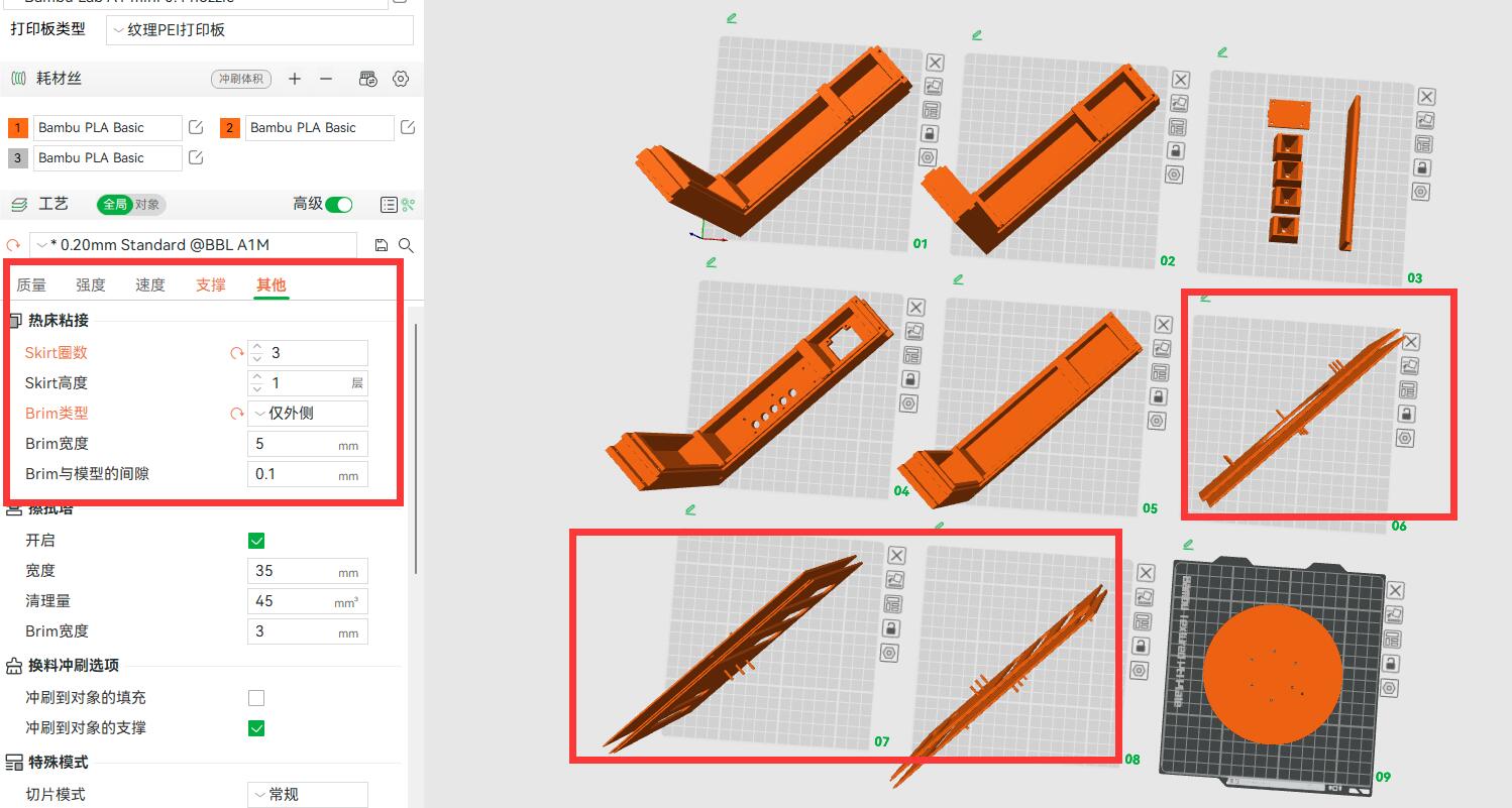
Project source · DIY cooling项目来源 · DIY 压风式散热器 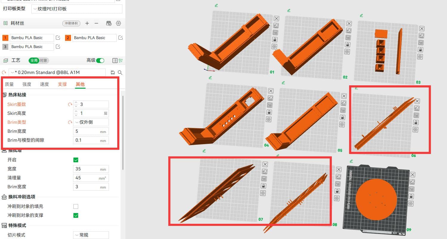 03.03Image图像
Brim and Skirt Settings That Never Reached the Printer没有走到打印的 Brim 与 Skirt 设置
The unprinted enclosure used three skirt loops, a 5 mm outer brim, and a 0.1 mm gap in this slicing pass. These settings record preparation, not a fabricated result.这次切片为未打印外壳设置了三圈 Skirt、5 mm 外侧 Brim 与 0.1 mm 间隙;这些参数只记录准备过程,不代表制造结果。
Project source · DIY cooling项目来源 · DIY 压风式散热器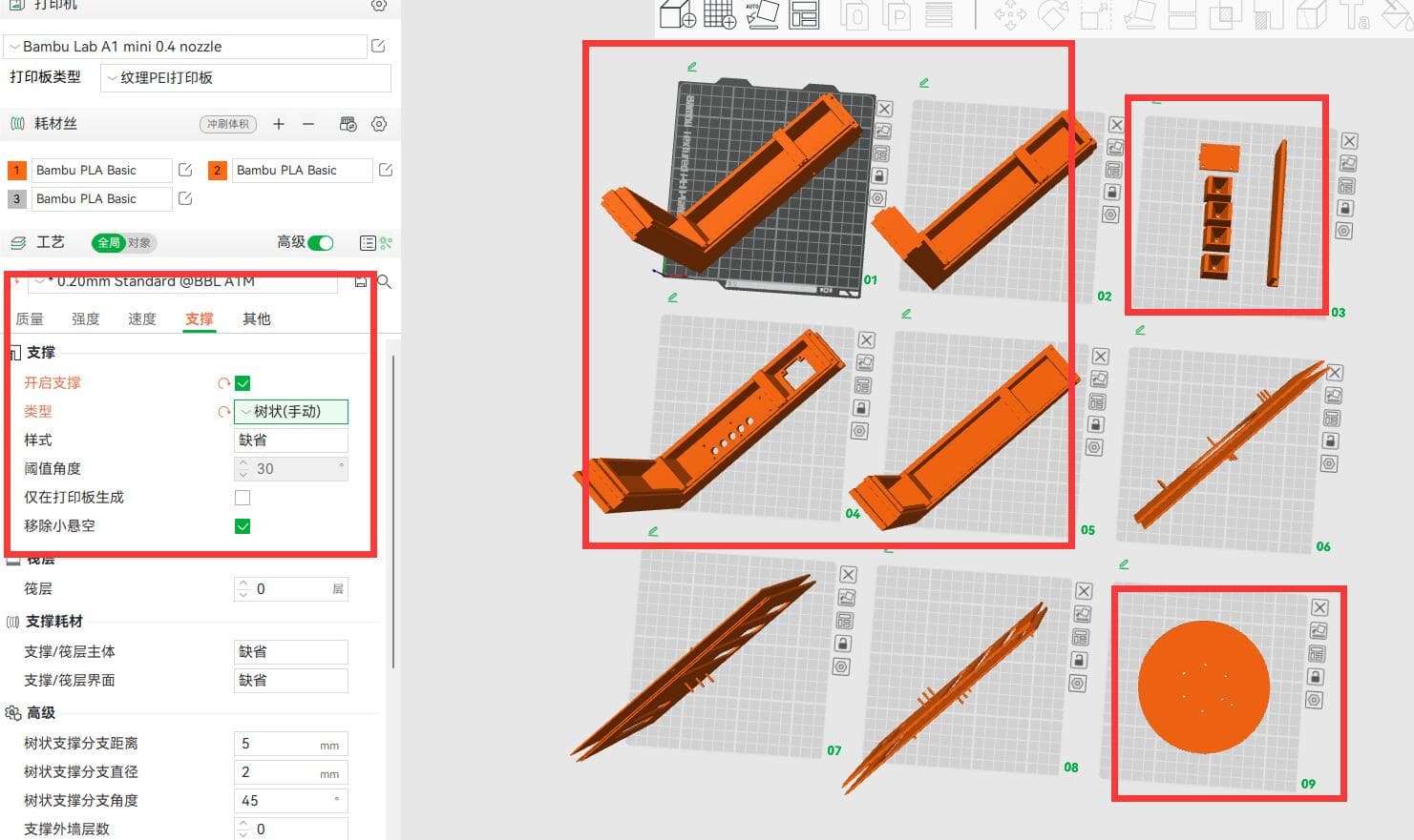 03.04Image图像
Reorienting the Enclosure Parts With Manual Tree Supports手动支撑下重新摆放外壳分件
A manual-tree-support pass compares orientations for the same enclosure parts. This mechanical revision remained a model and slicing study.手动树状支撑方案比较了同一组外壳分件的摆放姿态;这版机械结构停留在模型与切片研究阶段。
Project source · DIY cooling项目来源 · DIY 压风式散热器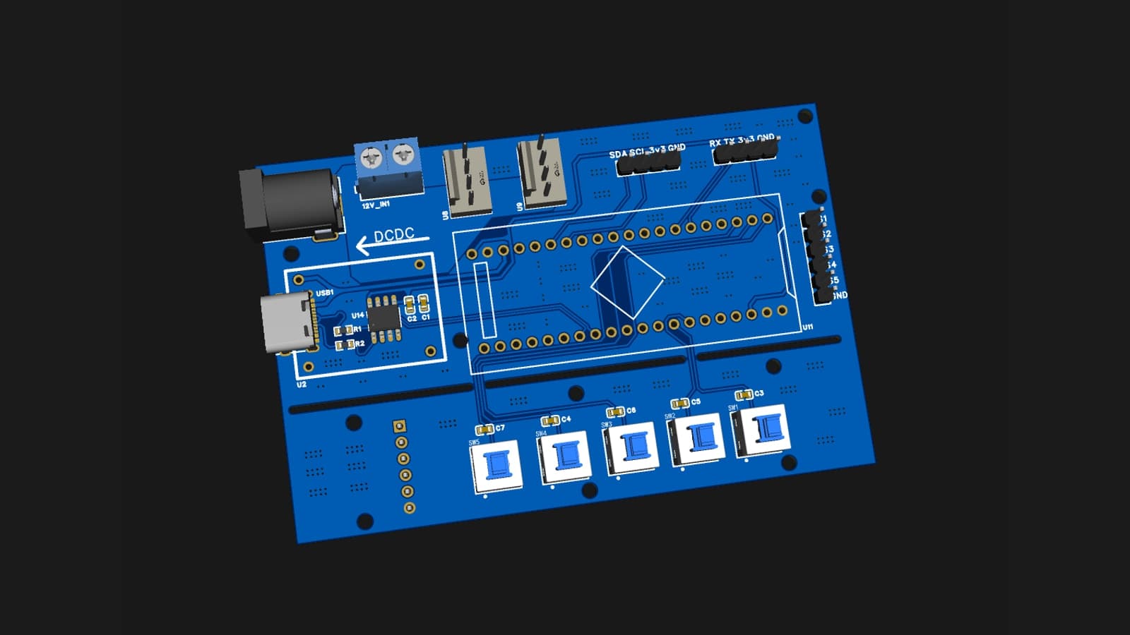 03.05Image图像
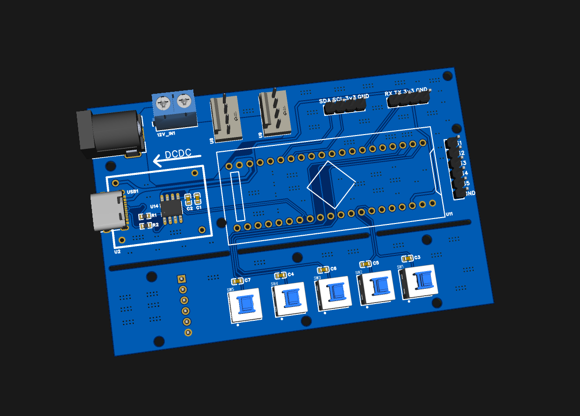
A Tighter STM32 Board Without the Complete Wireless Chain更紧凑、但未接回完整无线链路的 STM32 板
The STM32 revision reorganized routing and reduced board size while retaining 12 V input, USB-C, two fan interfaces, OLED/Bluetooth headers, and five buttons. The PCB was soldered, powered, and tested by serial fan commands, but not installed in the cooler.STM32 版本重新整理走线并缩小板卡,同时保留 12 V 输入、USB-C、两路风扇、OLED / Bluetooth 排针和五个按键;PCB 完成焊接、上电与串口风扇命令测试,但没有装入散热器。
Project source · DIY cooling项目来源 · DIY 压风式散热器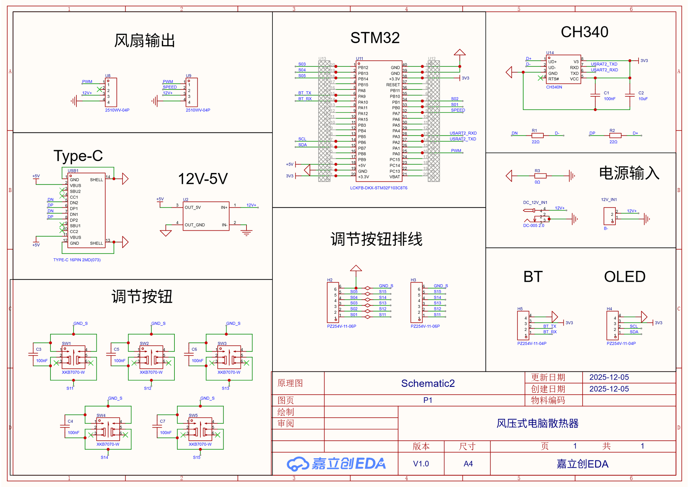 03.06Image图像
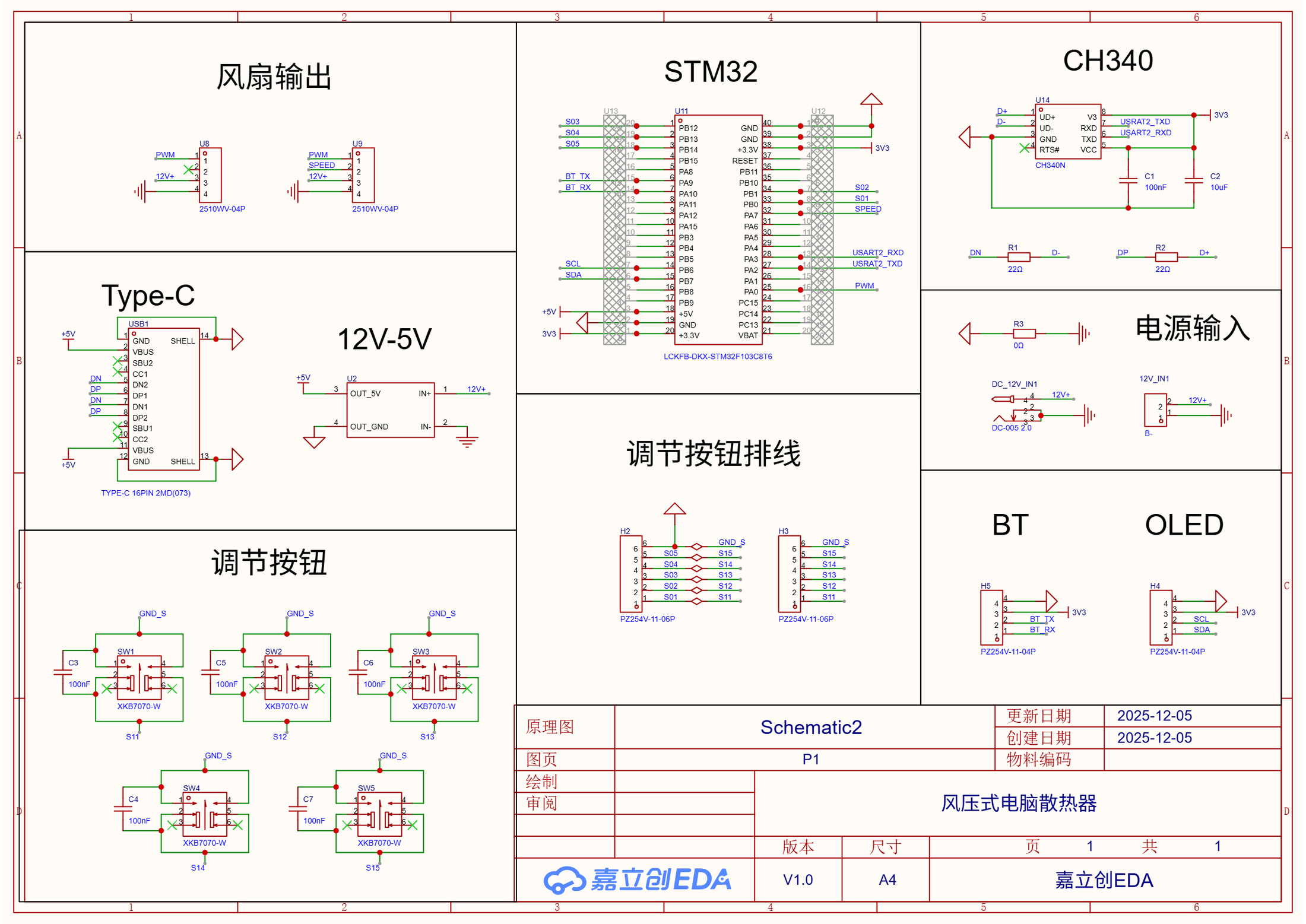
USB-UART and Dual-Fan Interfaces on the STM32 VersionSTM32 版的 USB-UART 与双风扇接口
The schematic combines an STM32F103C8T6, CH340N USB-UART, dual fan interfaces, 12 V-to-5 V conversion, five buttons, and OLED/Bluetooth headers. Serial fan control was tested; the Windows automatic-temperature path was not restored.原理图组合了 STM32F103C8T6、CH340N USB-UART、双风扇接口、12 V 转 5 V、五个按键及 OLED / Bluetooth 排针;串口风扇控制完成测试,Windows 自动温度链路没有恢复。
Project source · DIY cooling项目来源 · DIY 压风式散热器
Seamly2D Qt Development Internship南京图灵 Seamly2D 开发实习
In a three-week internship, I brought an unfamiliar Qt codebase into operation, added local accounts and role management, and prepared a Windows installer and an unsigned macOS package for review and handoff.三周实习里,我从配置 Qt、编译陌生代码库开始,为 Seamly2D 加入本地账户和角色管理,再完成 Windows 安装包与 macOS 无签名包的演示和交接。
- Records记录
- 019
- Images图像
- 019
- Videos视频
- 000
 04.01Image图像
The upstream application behind the internship这段实习所基于的 Seamly2D 上游项目
Seamly2D is the open-source patternmaking application I brought up, extended with a local account layer, and packaged during the three-week Qt internship; the upstream software and wordmark are not my work.三周 Qt 实习围绕 Seamly2D 展开。我跑通上游工程、加入本地账户层并尝试打包;软件本体与项目标识并非我的作品。
Project source · Nanjing Qt log项目来源 · 南京图灵 Qt 实习 04.02Image图像
Three weeks of full-time Qt development in Nanjing南京三周全职 Qt 实习
The portfolio cover places the work in its Nanjing internship context. The institute mark is existing institutional material, not a personal logo design.这张封面交代南京线下实习背景;研究院标识属于既有机构材料,并非个人 Logo 设计。
Project source · Nanjing Qt log项目来源 · 南京图灵 Qt 实习 04.03Image图像
The Qt Kit that finally matched the source终于与源码配对的 Qt Kit
The first full build worked only after Qt 6.5.3 MSVC2019 64-bit, the v142 compiler, qmake, architecture, and Kit selection agreed. The Qt mark itself is upstream brand material.Qt 6.5.3 MSVC2019 64-bit、v142 编译器、qmake、架构与 Kit 对齐后,完整构建才通过;Qt 标识本身属于上游品牌材料。
Project source · Nanjing Qt log项目来源 · 南京图灵 Qt 实习 04.04Image图像
CMake study beside a qmake project在 qmake 项目旁展开的 CMake 学习
I studied CMake, generators, toolchains, and package discovery in parallel while Seamly2D itself remained on qmake; the CMake mark is upstream brand material.我并行学习了 CMake、生成器、工具链与包发现,但 Seamly2D 本身始终使用 qmake;CMake 标识属于上游品牌材料。
Project source · Nanjing Qt log项目来源 · 南京图灵 Qt 实习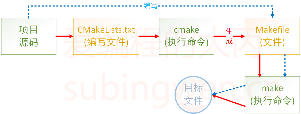 04.05Image图像
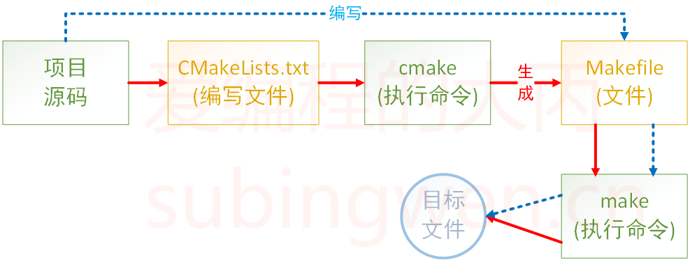
Separating rule generation from build execution把规则生成与构建执行分开
This upstream tutorial diagram helped separate CMake's generation of a Makefile from make's execution of the resulting rules; it was saved as study material, not drawn by me.这张上游教程图把 CMake 生成 Makefile 与 make 执行规则分开表示;它是我保存的学习资料,并非个人绘图。
Project source · Nanjing Qt log项目来源 · 南京图灵 Qt 实习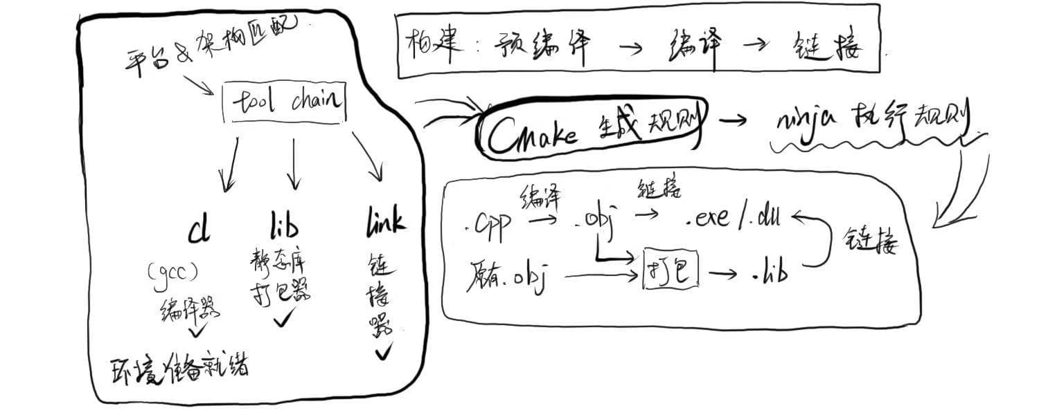 04.06Image图像
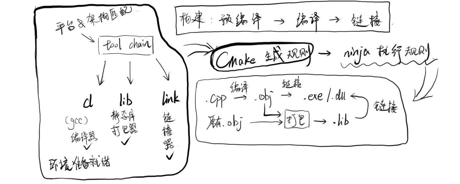
Build-toolchain archive sketch构建工具链档案草图
A handwritten sketch preserved in the internship archive groups toolchain setup, CMake/Ninja rules, and compiler/linker outputs; the file does not identify its author.实习档案中保留的手绘草图,把工具链配置、CMake/Ninja 规则与编译器/链接器产物放在一起;文件没有注明作者。
Project source · Nanjing Qt log项目来源 · 南京图灵 Qt 实习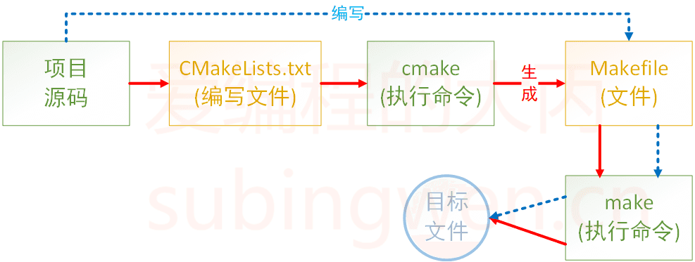 04.07Image图像
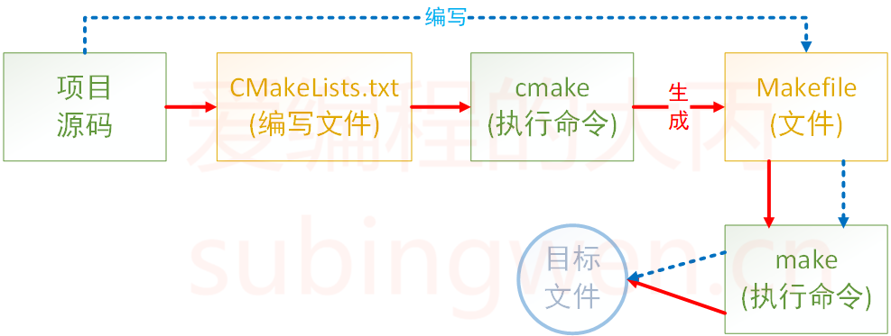
Notion-export copy of the CMake-to-Make tutorial diagramCMake 到 Make 教程图的 Notion 导出副本
The Notion export embeds a copy of the same upstream tutorial diagram shown above; it is a duplicate asset, not a separate CMake flow artifact.Notion 导出嵌入的是上方同一张上游教程图的副本;这是重复资产,不是另一张独立的 CMake 流程图。
Project source · Nanjing Qt log项目来源 · 南京图灵 Qt 实习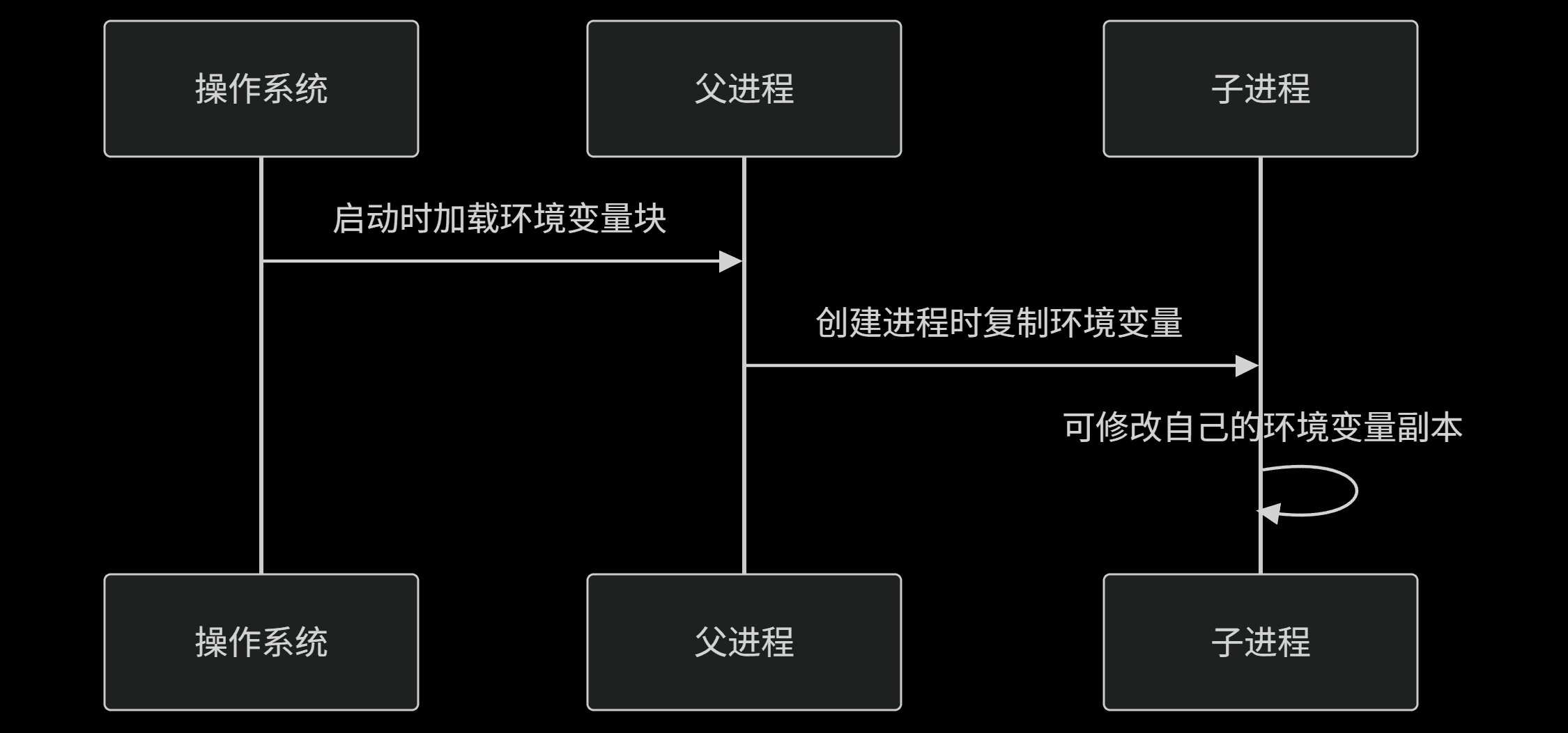 04.08Image图像
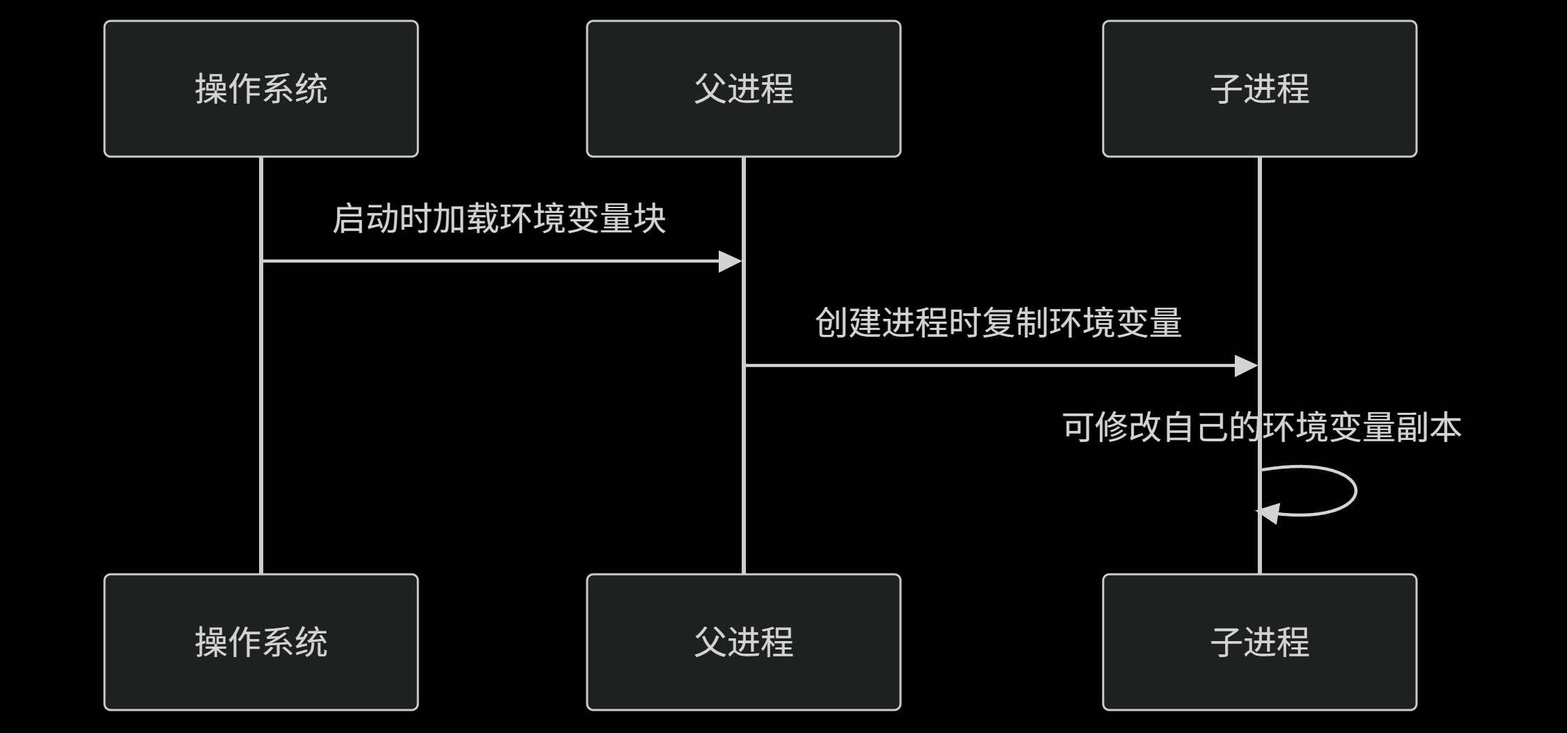
Parent-child environment-variable flow父子进程的环境变量流向
One DeepSeek-generated Mermaid export in the Notion build note shows environment variables loading into a parent process, then being copied to a child process.Notion 编译笔记中的 DeepSeek 生成 Mermaid 图,表示环境变量进入父进程后再复制给子进程。
Project source · Nanjing Qt log项目来源 · 南京图灵 Qt 实习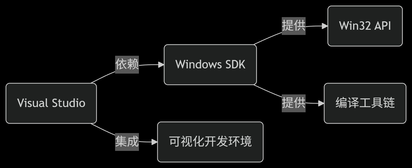 04.09Image图像
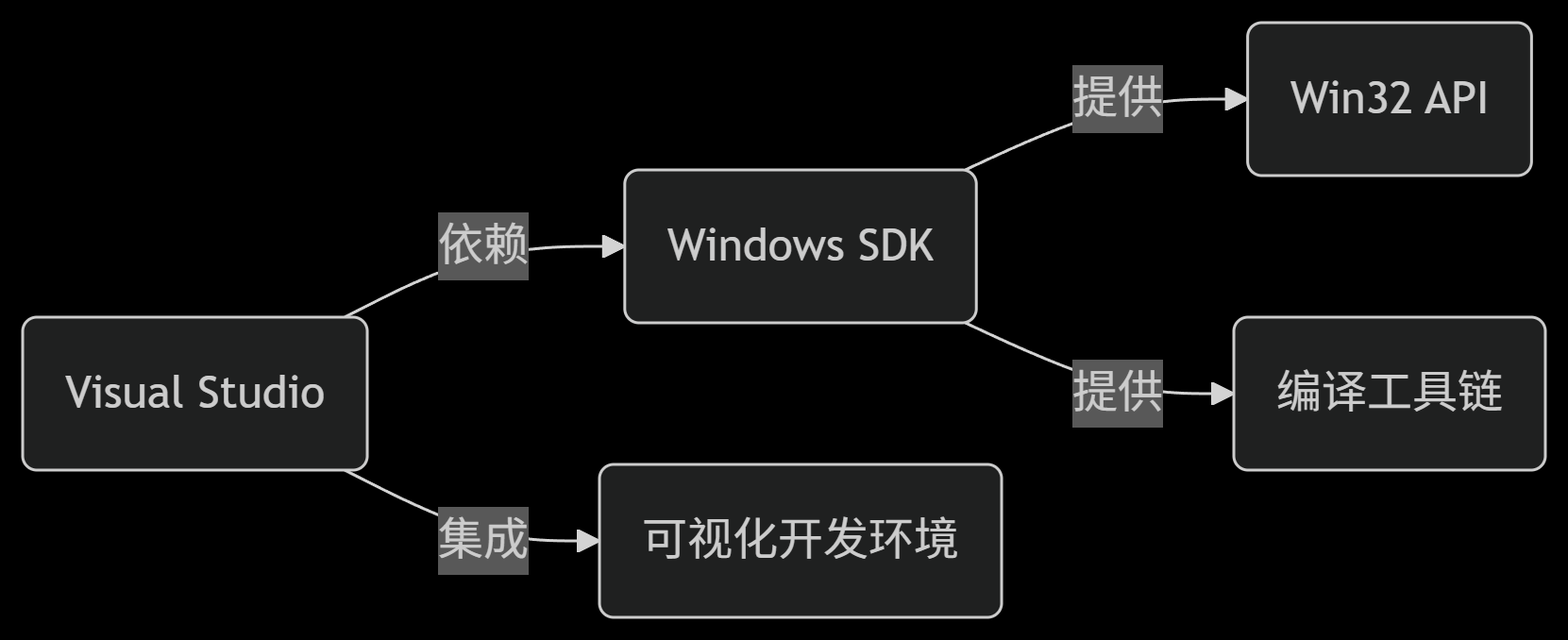
Visual Studio, Windows SDK, and toolchain mapVisual Studio、Windows SDK 与工具链关系图
This generated Mermaid map from the Notion note places Visual Studio beside its integrated development environment, Windows SDK, Win32 API, and compiler toolchain.Notion 笔记中的生成式 Mermaid 关系图,把 Visual Studio、集成开发环境、Windows SDK、Win32 API 与编译工具链放在同一张图上。
Project source · Nanjing Qt log项目来源 · 南京图灵 Qt 实习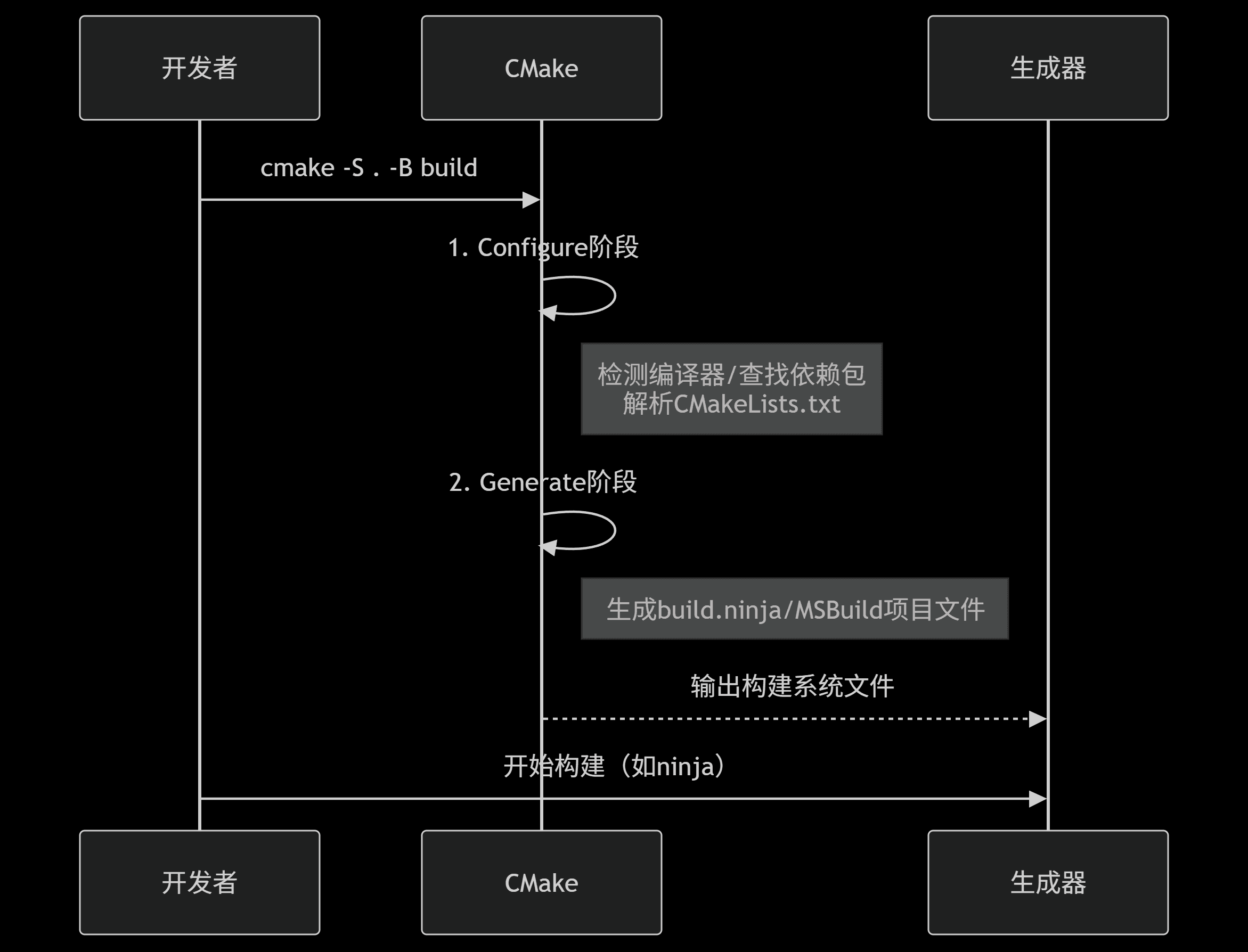 04.10Image图像
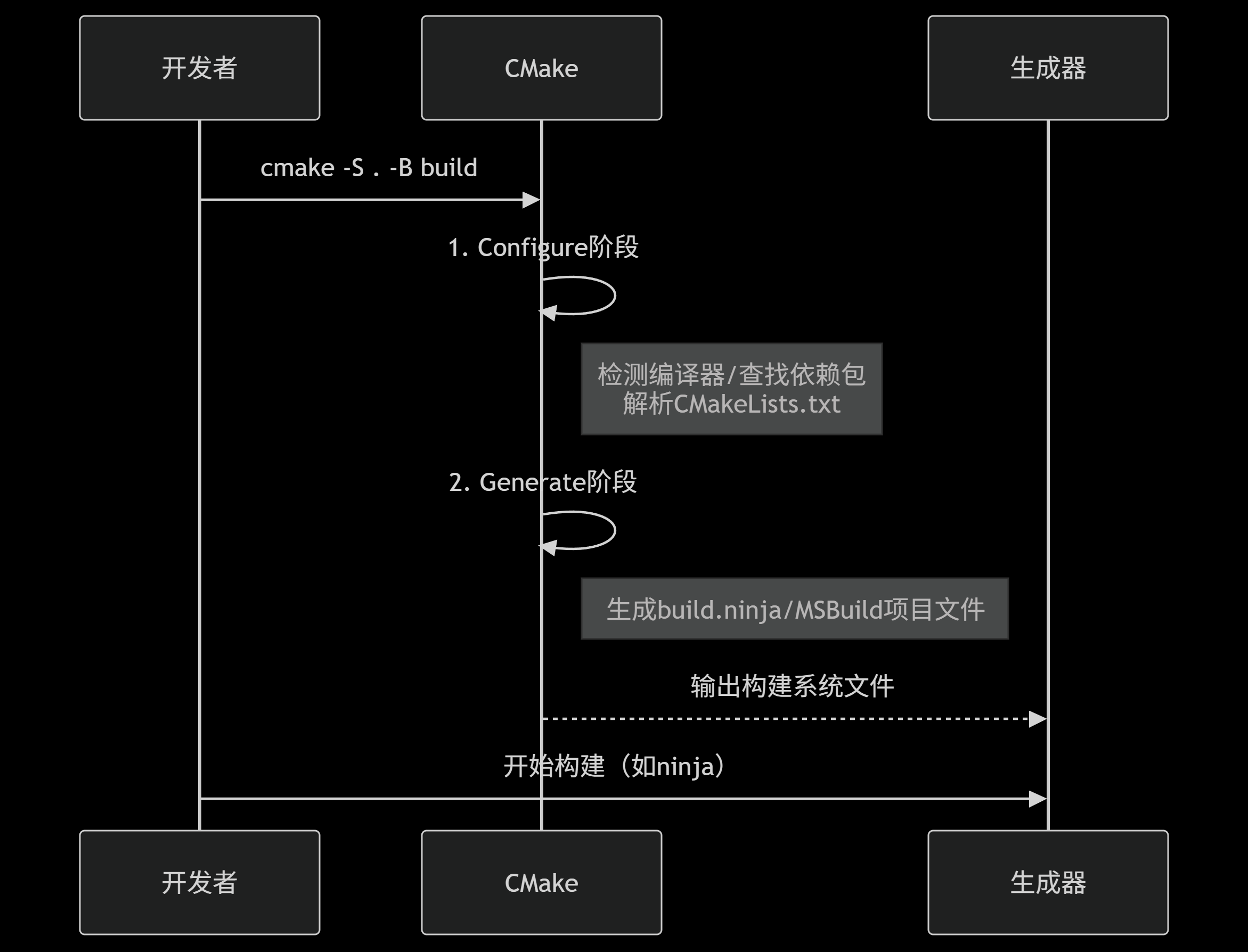
CMake configure-and-generate sequenceCMake 配置与生成阶段时序图
A DeepSeek-generated sequence diagram separates CMake's configure and generate stages before handing the generated build files to a native build tool.DeepSeek 生成的时序图把 CMake 的 Configure 与 Generate 阶段分开,再将生成的构建文件交给本机构建工具执行。
Project source · Nanjing Qt log项目来源 · 南京图灵 Qt 实习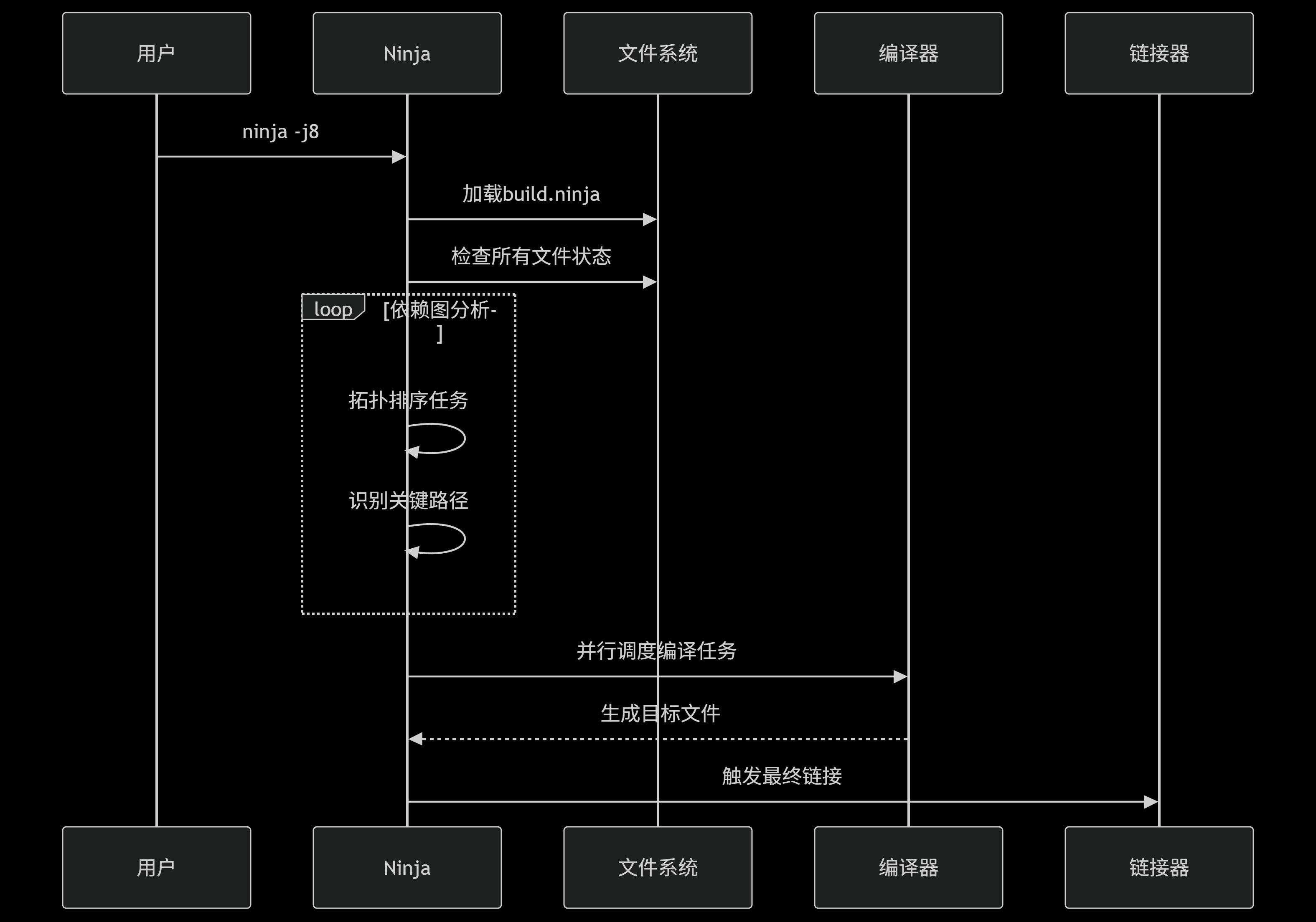 04.11Image图像
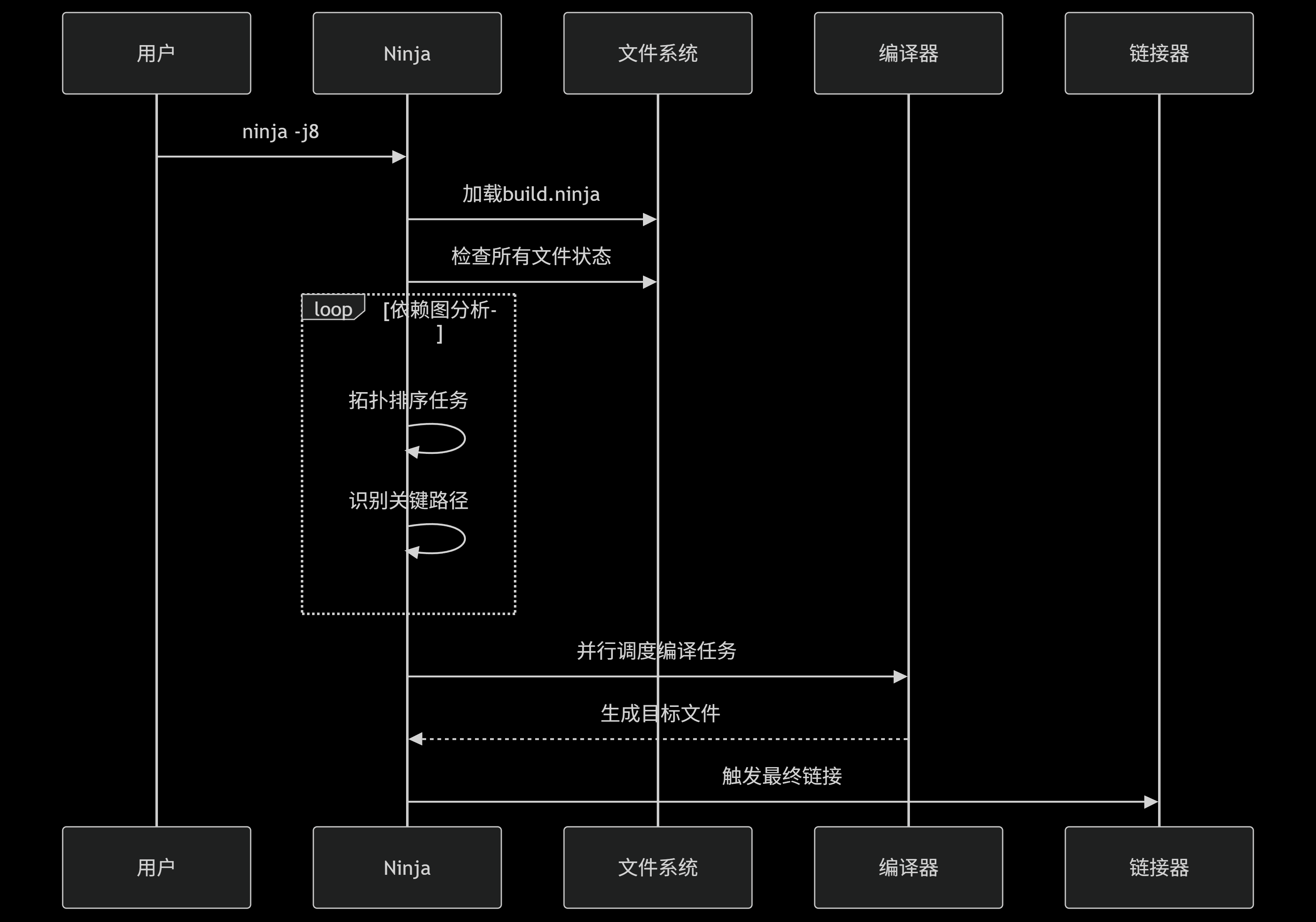
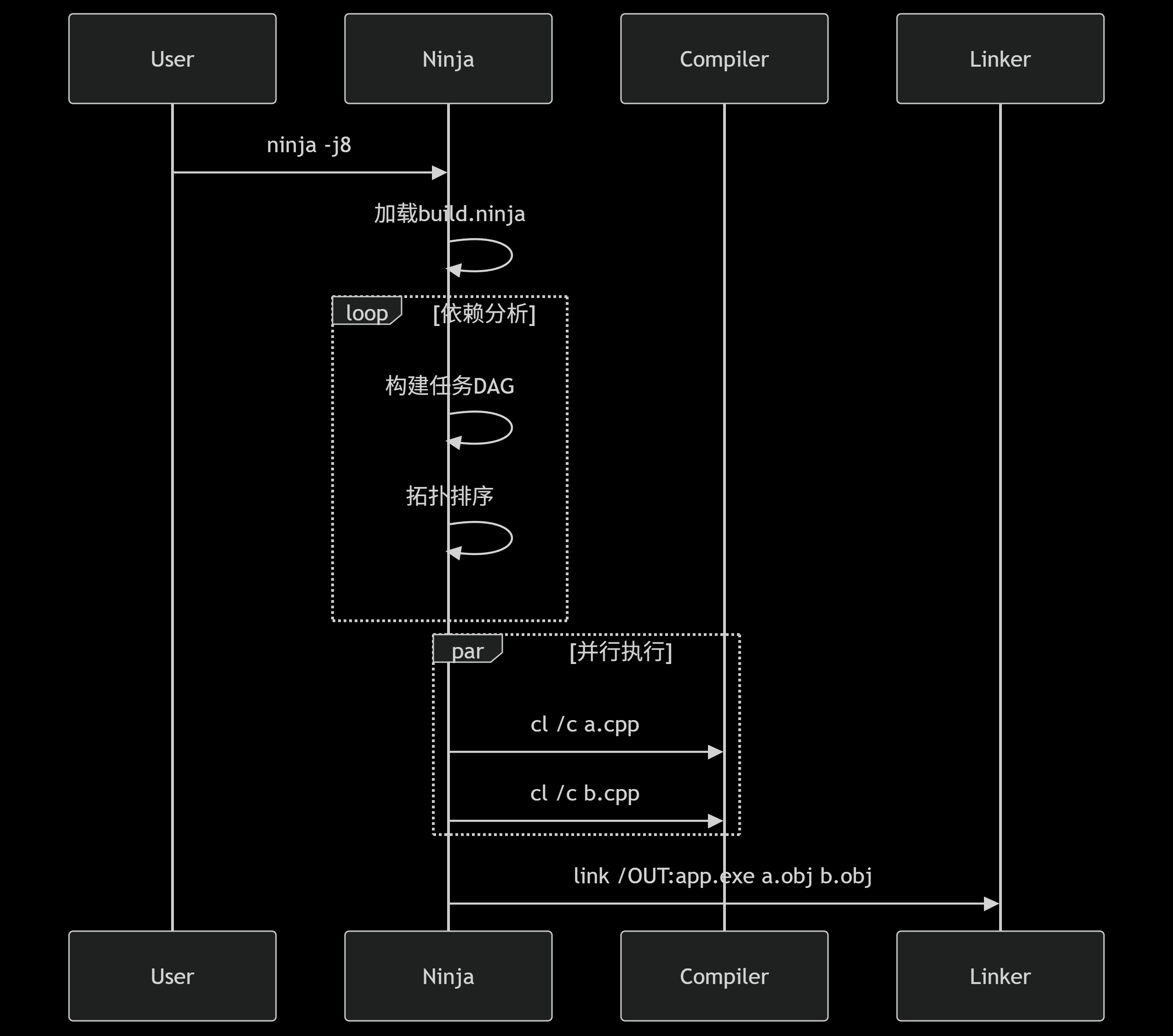
Ninja dependency-scheduling sequenceNinja 依赖调度时序图
The generated sequence follows Ninja as it loads build.ninja, checks files, orders the dependency graph, schedules compile tasks, and invokes the linker.生成式时序图跟随 Ninja 读取 build.ninja、检查文件、排列依赖图、调度编译任务并调用链接器。
Project source · Nanjing Qt log项目来源 · 南京图灵 Qt 实习 04.12Image图像
CMake rule-generation pathCMake 构建规则生成路径
A compact DeepSeek-generated flow in the source note moves from CMakeLists.txt through project parsing, dependency analysis, platform adaptation, and native build-rule output.原始笔记中的 DeepSeek 生成流程图,从 CMakeLists.txt 依次经过项目解析、依赖分析、平台适配与本机构建规则输出。
Project source · Nanjing Qt log项目来源 · 南京图灵 Qt 实习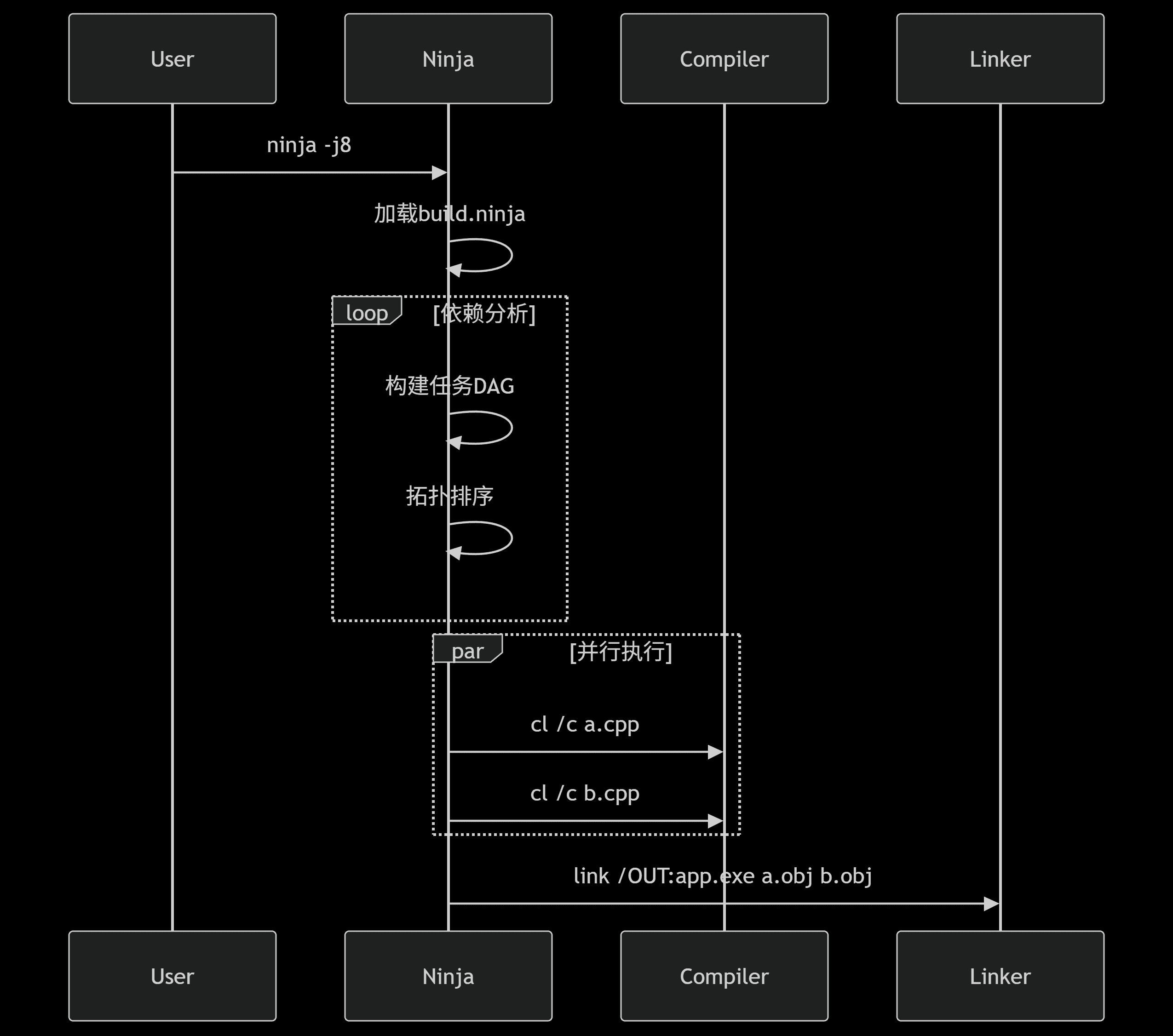 04.13Image图像
Ninja compile-and-link sequenceNinja 编译与链接时序图
This DeepSeek-generated Mermaid export makes the division visible. Ninja schedules the DAG, compiler jobs produce objects, and the linker emits the executable.DeepSeek 生成的 Mermaid 图把分工画开。Ninja 调度依赖图,编译器生成目标文件,链接器再产出可执行程序。
Project source · Nanjing Qt log项目来源 · 南京图灵 Qt 实习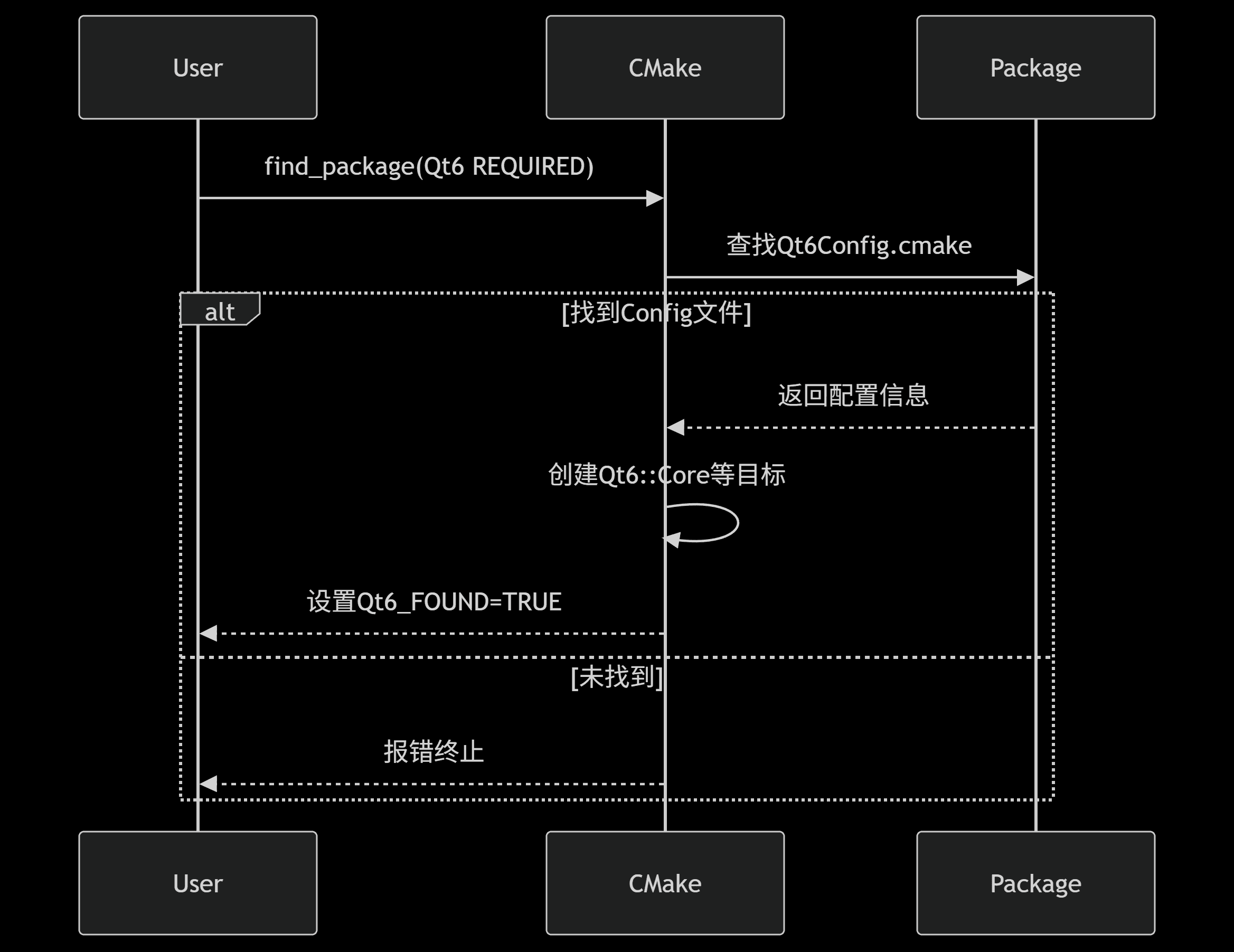 04.14Image图像
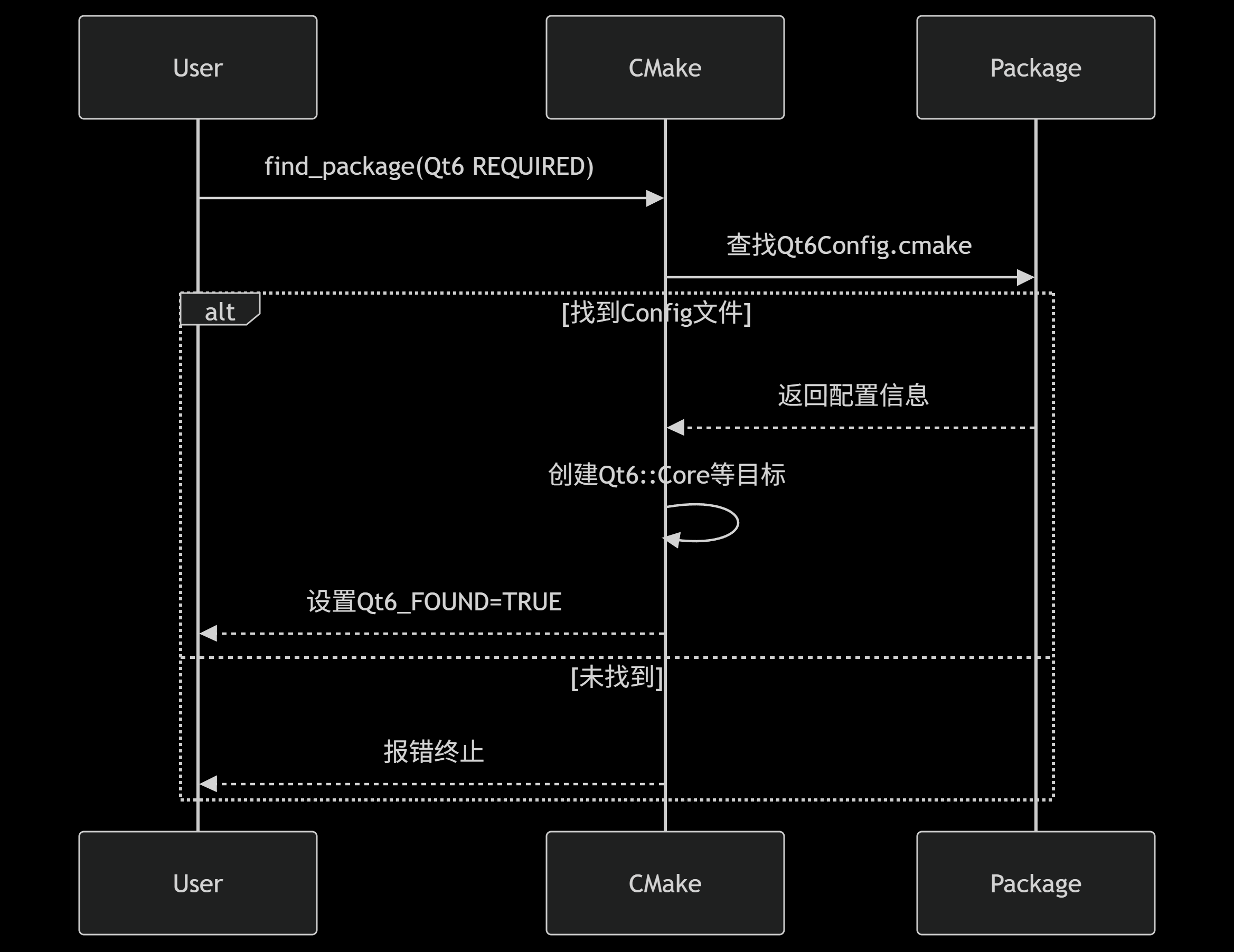
Qt 6 package-discovery sequenceQt 6 包发现时序图
The generated Qt 6 package-discovery sequence follows CMake to Qt6Config.cmake and imported targets such as the Qt 6 Core target, or to an error when the config is absent.生成式 Qt 6 包发现时序图跟随 CMake 查找 Qt6Config.cmake、创建 Qt 6 Core 等导入目标,未找到配置时则报错终止。
Project source · Nanjing Qt log项目来源 · 南京图灵 Qt 实习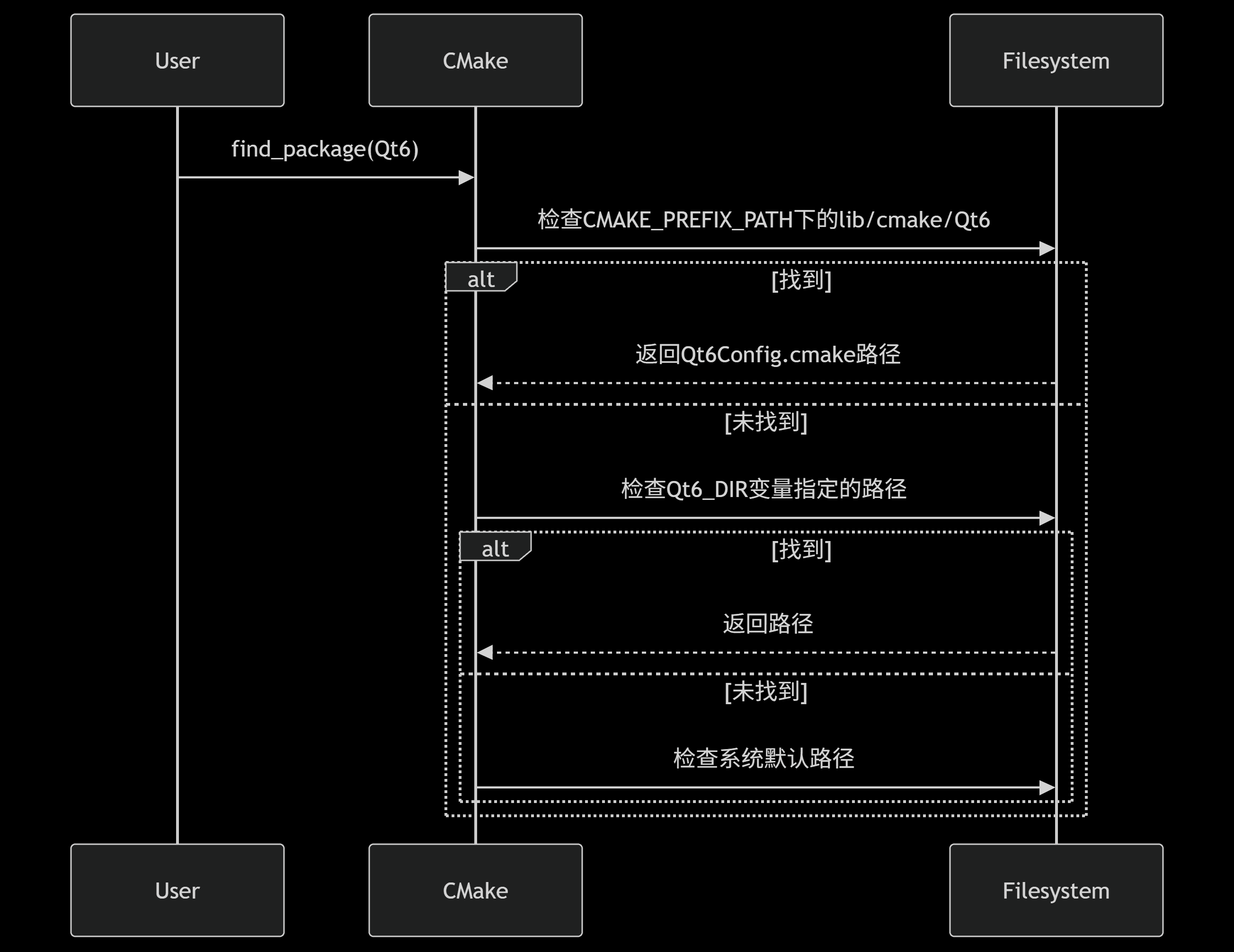 04.15Image图像
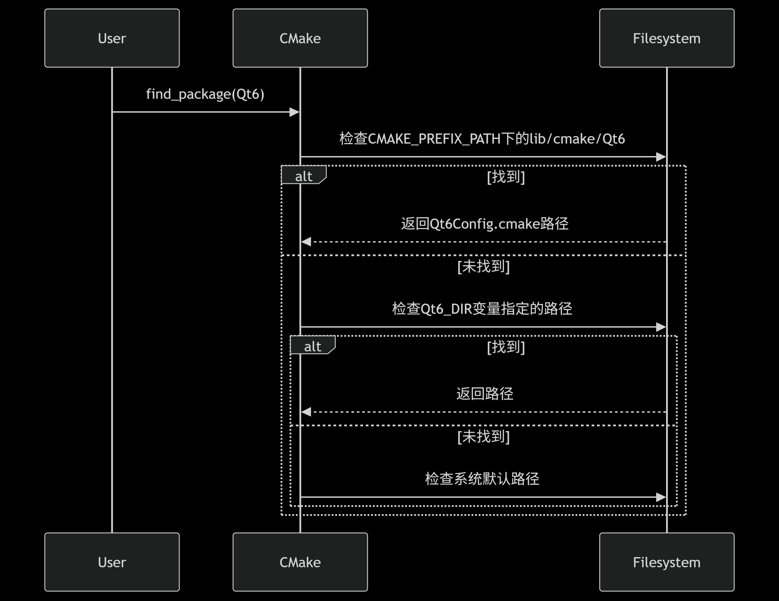
Qt 6 package search orderQt 6 包搜索顺序
Another generated diagram in the Notion note compares CMAKE_PREFIX_PATH, Qt6_DIR, and default system paths during Qt package discovery.Notion 笔记中的另一张生成图比较了 Qt 包发现时的 CMAKE_PREFIX_PATH、Qt6_DIR 与系统默认路径。
Project source · Nanjing Qt log项目来源 · 南京图灵 Qt 实习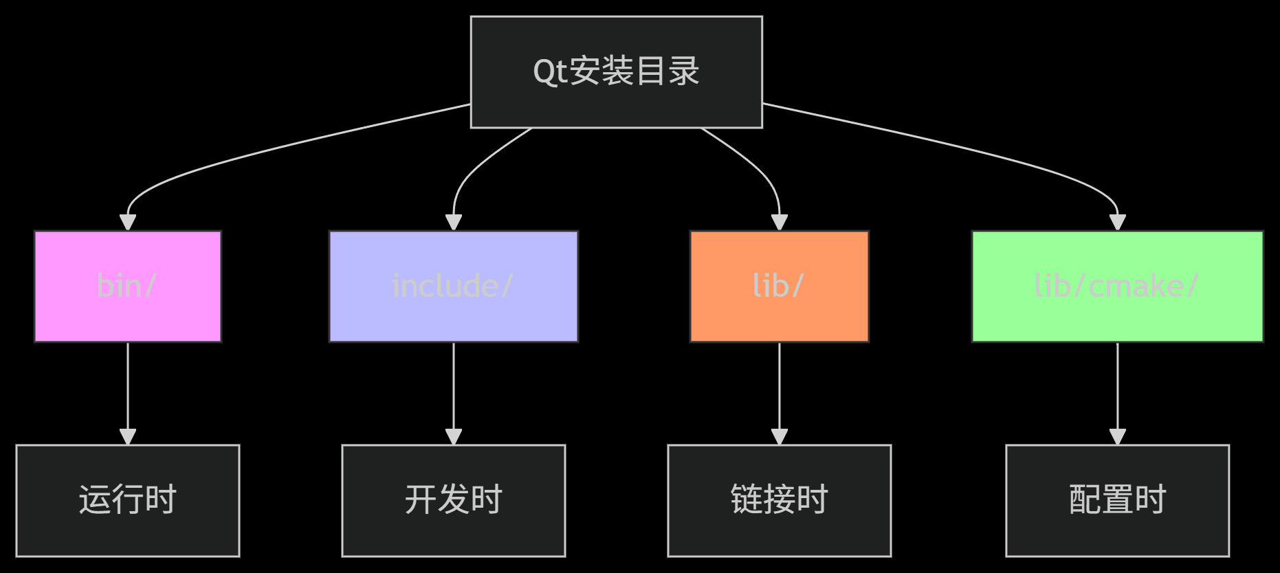 04.16Image图像
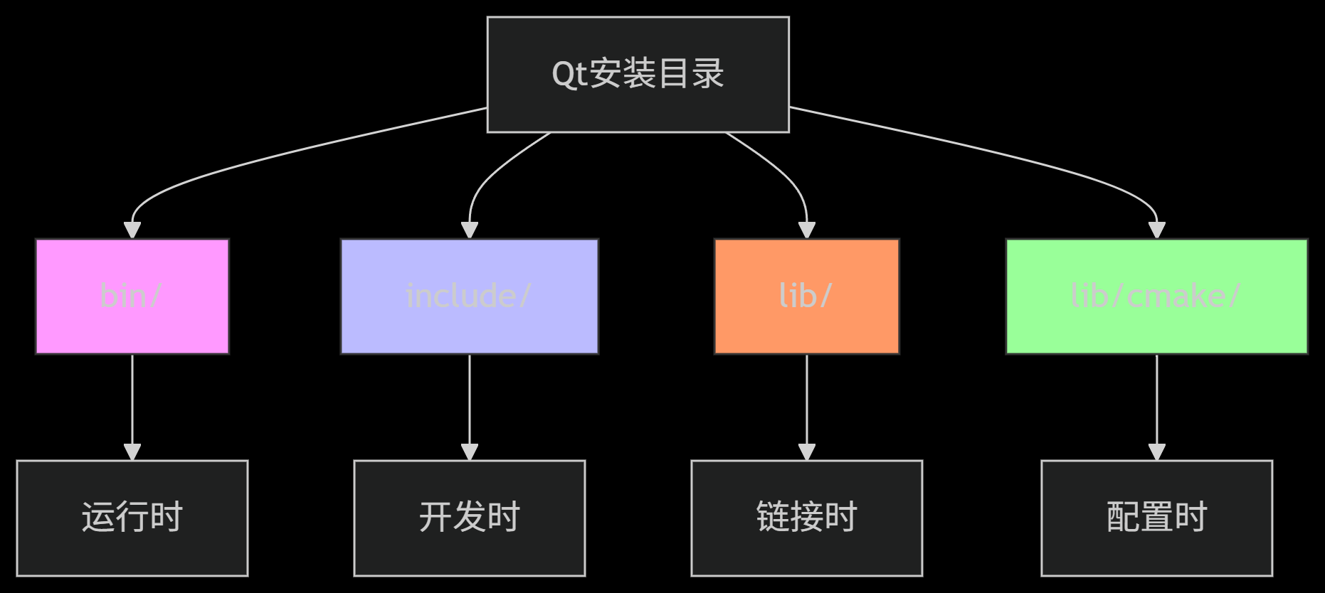
Qt installation directory rolesQt 安装目录分工图
The generated directory map labels bin for runtime tools, include for development headers, lib for link-time files, and lib/cmake for package configuration.生成式目录图把 bin 标为运行时工具区、include 标为开发头文件区、lib 标为链接文件区,lib/cmake 则放包配置。
Project source · Nanjing Qt log项目来源 · 南京图灵 Qt 实习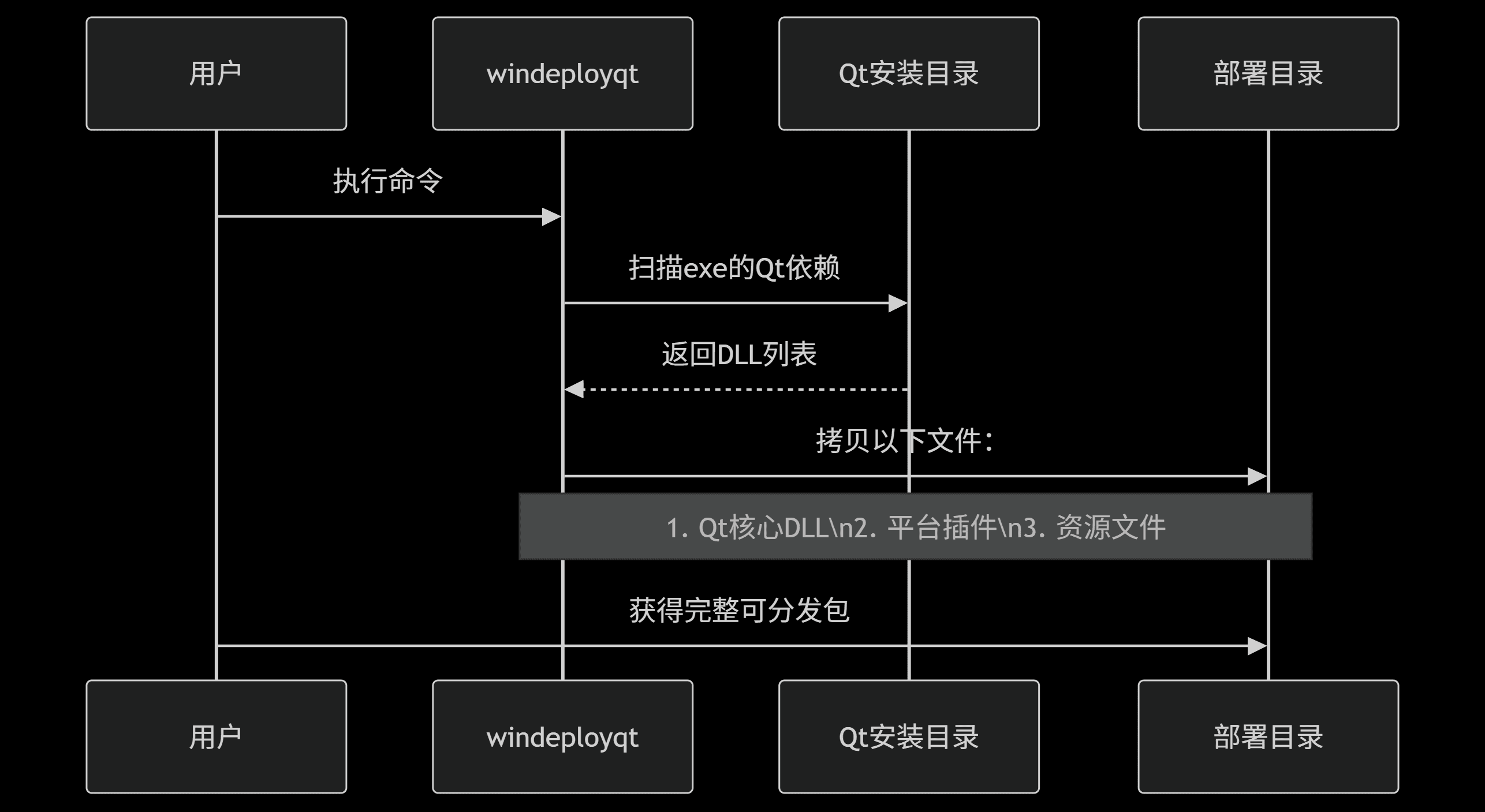 04.17Image图像
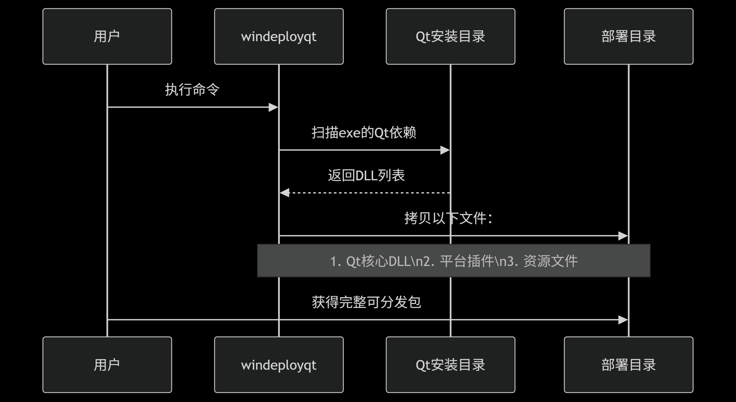
windeployqt dependency-collection sequencewindeployqt 依赖收集时序图
A generated sequence diagram shows windeployqt scanning an executable's Qt dependencies and copying core DLLs, platform plugins, and resources into a deployment directory.生成式时序图展示 windeployqt 扫描可执行程序的 Qt 依赖,并把核心 DLL、平台插件与资源复制到部署目录。
Project source · Nanjing Qt log项目来源 · 南京图灵 Qt 实习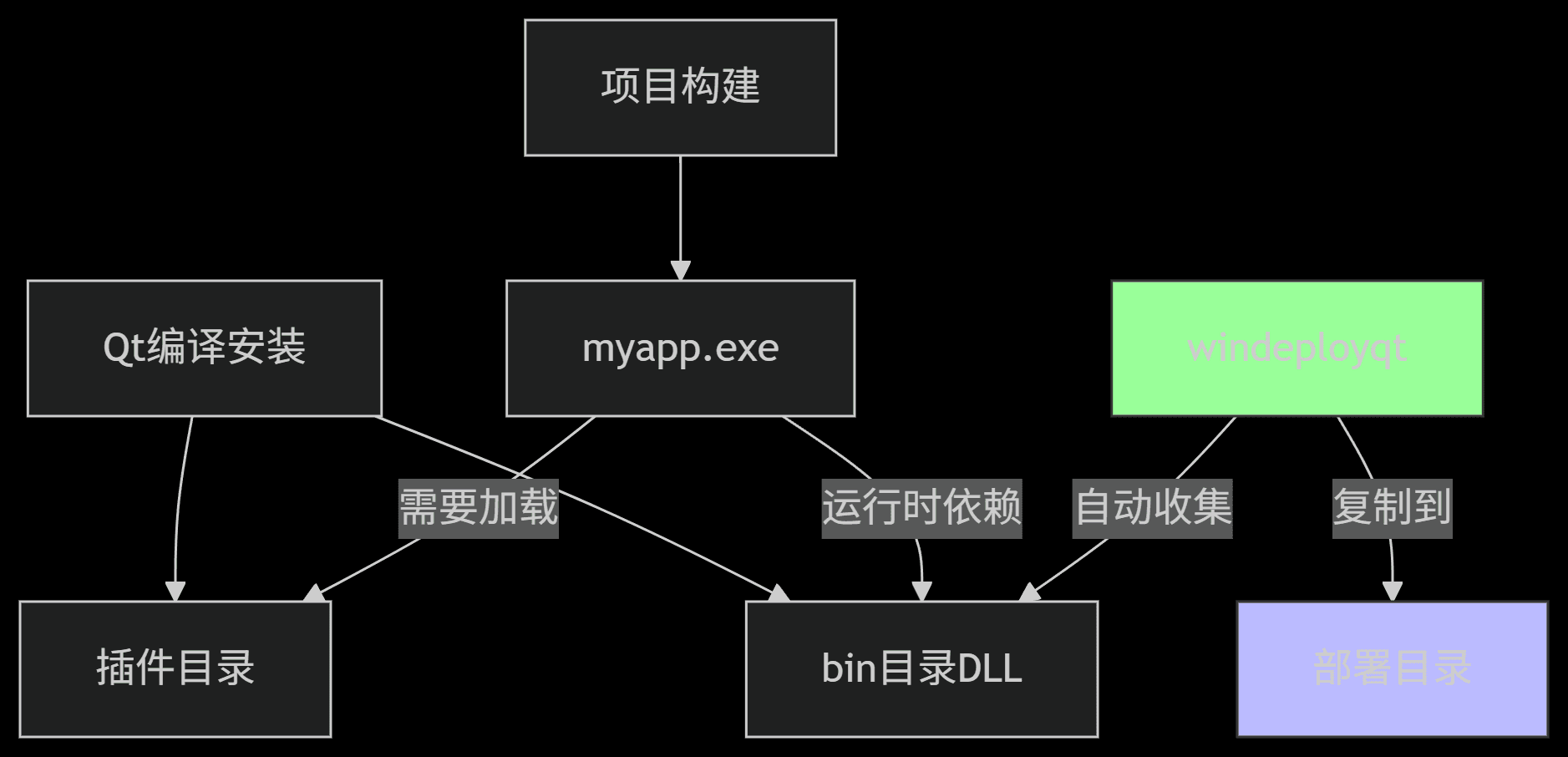 04.18Image图像
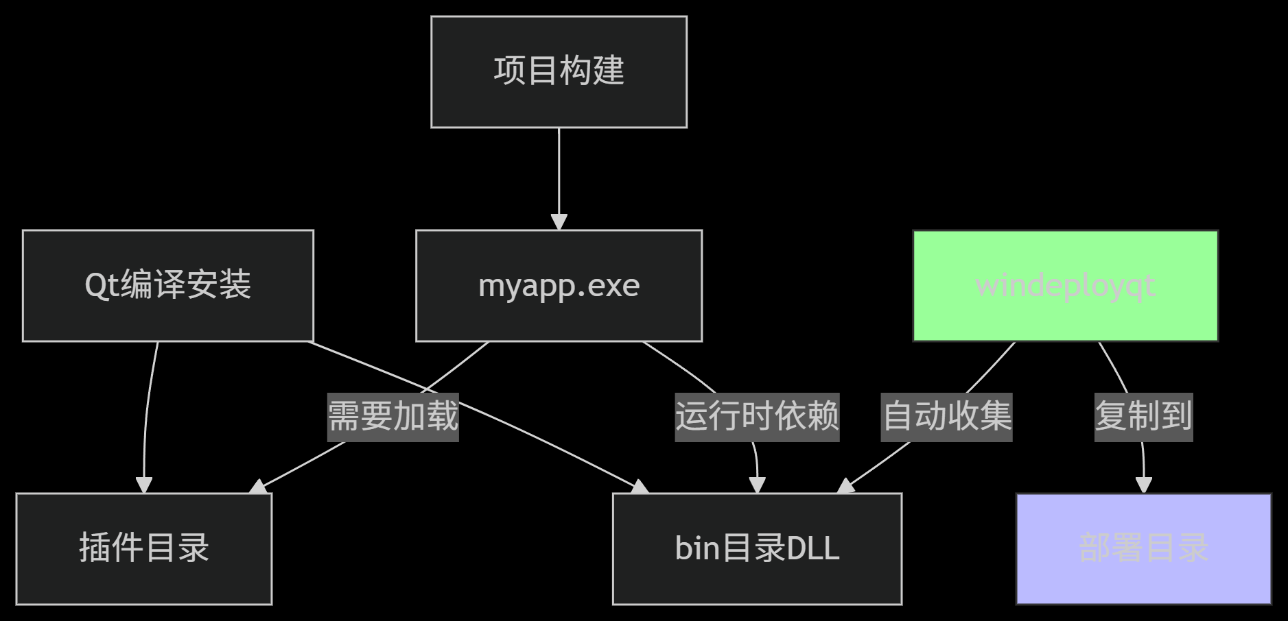
Qt runtime dependency mapQt 运行时依赖关系图
This DeepSeek-generated map connects the built executable, Qt DLL/plugin locations, and windeployqt's collection step; non-Qt libraries still need separate handling.DeepSeek 生成图串起已构建程序、Qt DLL/插件位置与 windeployqt 收集步骤;非 Qt 库仍需另行处理。
Project source · Nanjing Qt log项目来源 · 南京图灵 Qt 实习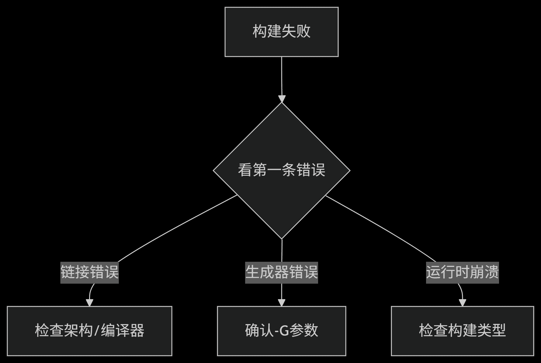 04.19Image图像
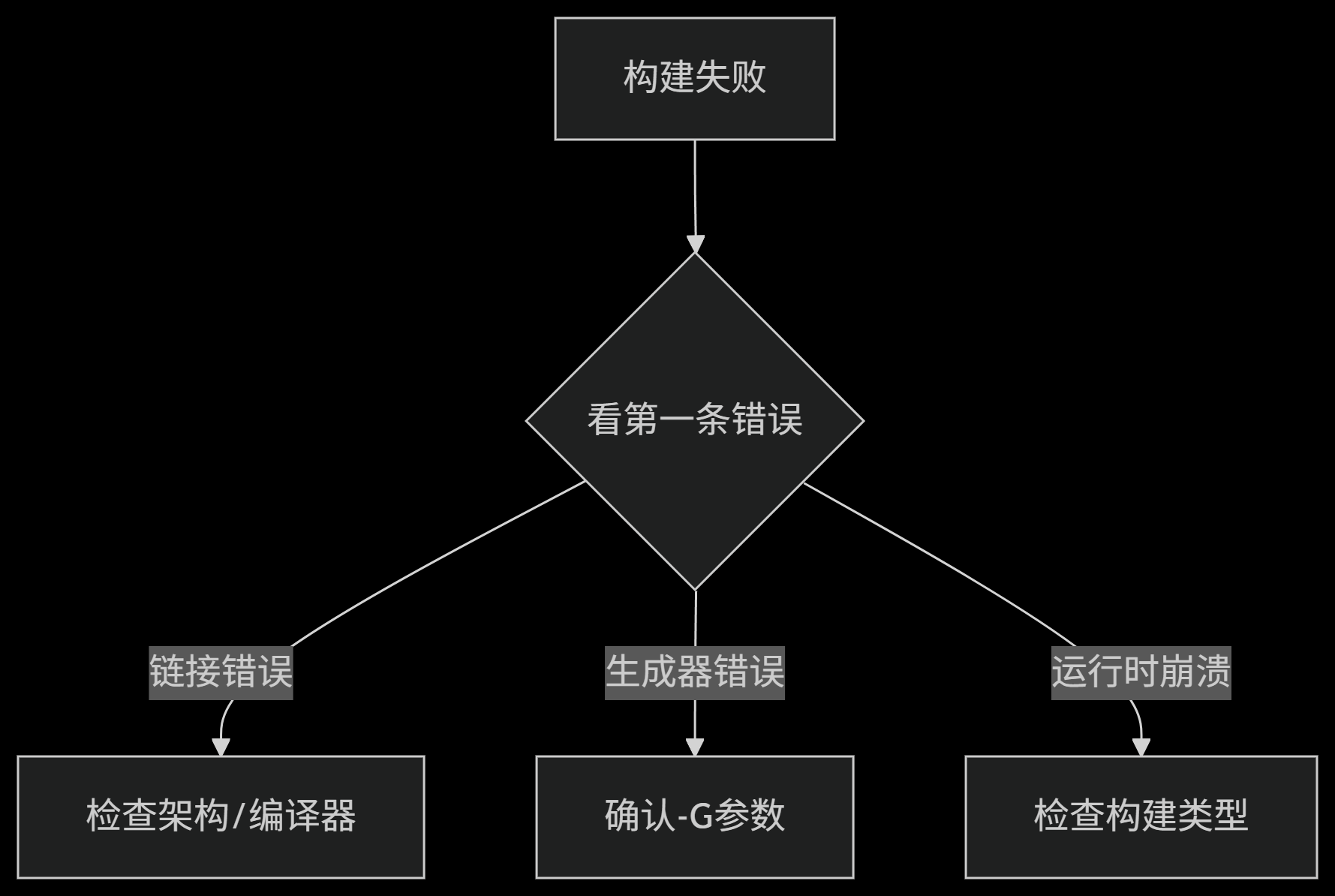
Build-failure first-check map构建失败的第一轮检查图
The final generated troubleshooting chart begins with the first error, then branches toward architecture/compiler, generator arguments, or build type according to the symptom.最后一张生成式排错图从第一条错误开始,再按现象分到架构/编译器、生成器参数或构建类型检查。
Project source · Nanjing Qt log项目来源 · 南京图灵 Qt 实习





Tianjin Jintie STM32 Internship天津津铁 STM32 嵌入式实习
During a month of foundational training at Tianjin Jintie, I planned my own STM32 learning sequence and combined external sensors, display, encoder, servo, and LED control in a working bare-metal demo.在天津津铁一个月的基础实习中,我自行安排 STM32 学习顺序,从外设小实验做起,最后把传感器、显示、编码器、舵机与 LED 控制接进同一套裸机演示。
- Records记录
- 003
- Images图像
- 003
- Videos视频
- 000
 05.01Image图像
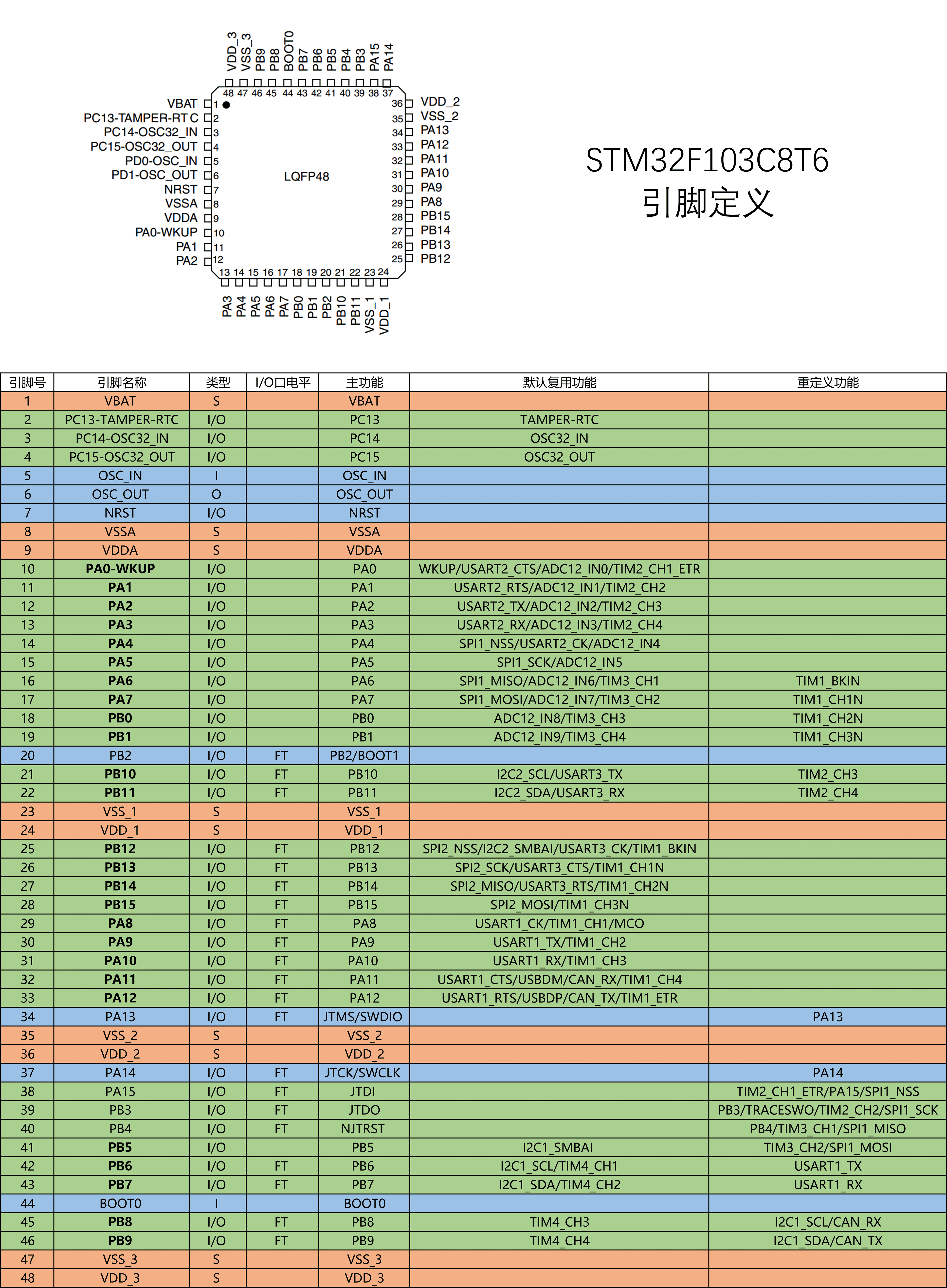
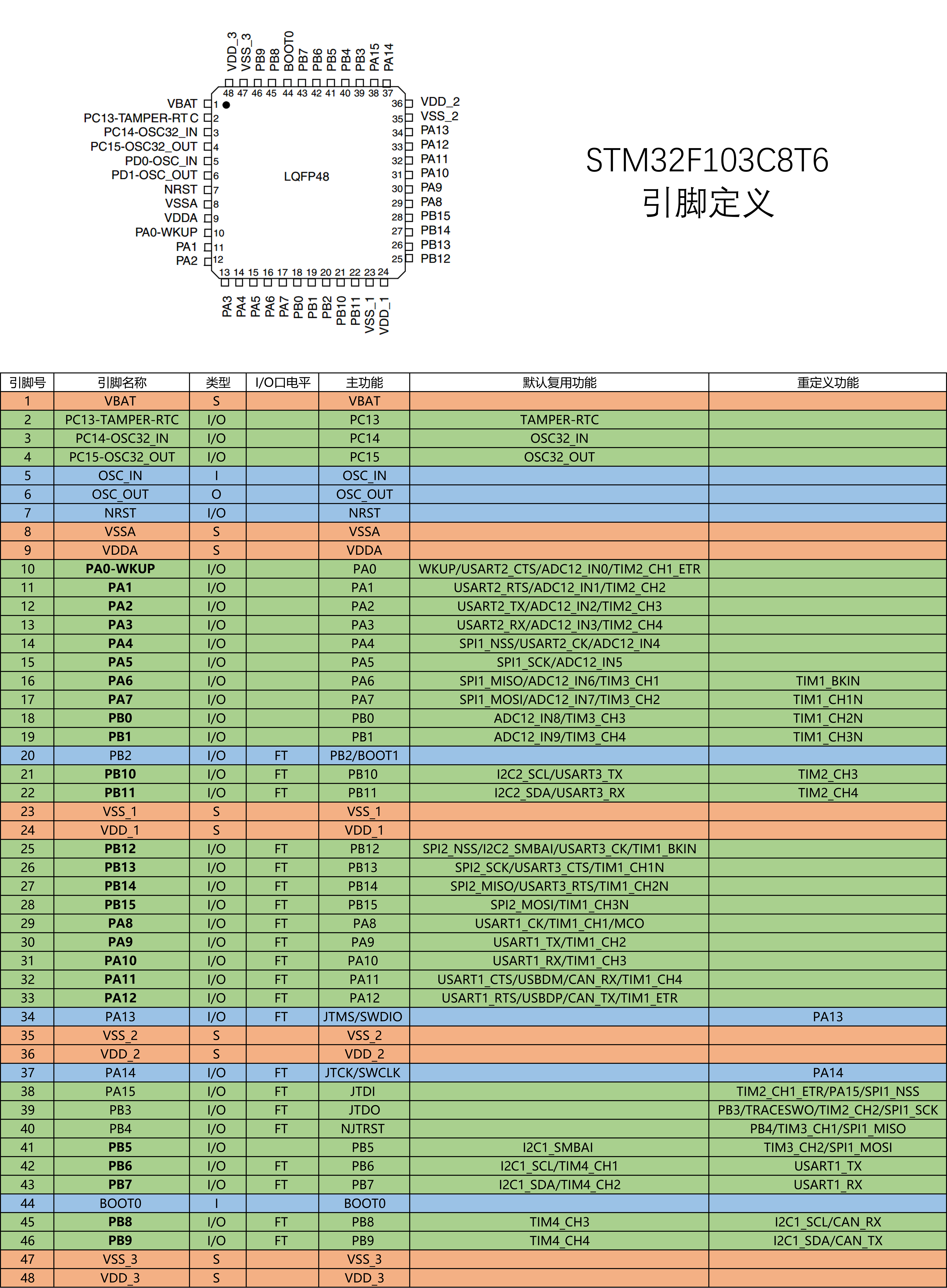
STM32F103C8T6 Pins and Alternate-Function ReferenceSTM32F103C8T6 引脚与复用功能参考
After moving from Arduino pin numbers to STM32 alternate functions, this LQFP48 map became my desk reference. GPIO, USART, ADC, and timers were no longer just function names but real pins whose ports, channels, and alternate mappings had to agree.从 Arduino 的引脚编号转到 STM32 外设复用后,这张 LQFP48 引脚图成了我的桌面地图。GPIO、USART、ADC 与 Timer 不再只是函数名,而是需要同时核对端口、通道和复用关系的真实引脚。
Project source · Tianjin STM32项目来源 · 天津津铁 STM32 实习 05.02Image图像
Tianjin Jintie Communications Embedded Internship Cover天津津铁通信嵌入式实习项目封面
This processed Tianjin Rail Transit mark records the setting of the work. I was an Embedded Systems Intern at Tianjin Jintie Communications, based in the Group headquarters, completing self-directed STM32 training and a bench demo rather than production rail-system development.这张处理后的天津轨道交通标志记录项目发生的实习语境。我以天津津铁通信嵌入式实习生身份在集团总部办公,完成的是 STM32 自学与培训 demo,并未参与生产轨道系统开发。
Project source · Tianjin STM32项目来源 · 天津津铁 STM32 实习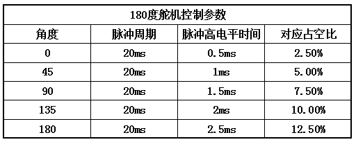 05.03Image图像
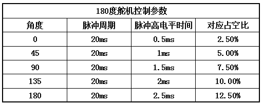
180° Servo Pulse Reference Table180° 舵机脉宽参考表
The servo exercise used this table to map a 0.5–2.5 ms high time within a 20 ms period onto 0°–180°. It is a Timer/PWM setup reference, not an oscilloscope measurement.舵机练习用这张表把 20 ms 周期内的 0.5–2.5 ms 高电平时间对应到 0°–180°。它是配置 Timer/PWM 时使用的参数参考,不是示波器实测波形。
Project source · Tianjin STM32项目来源 · 天津津铁 STM32 实习

Arduino Breadboard Two-Digit Seven-Segment CounterArduino 面包板两位数码管计数器
For MEC104 Group A17, I handled most of the two-digit counter’s wiring, firmware, and debugging. Testing the display segments and measuring switch contacts resolved faults that code changes had not.我承担 MEC104 A17 组两位计数器的大部分搭建、编程与调试。数码管接法和六脚按键先后出问题,我通过逐段试灯、测量开关通断,把显示、暂停和复位调通。
- Records记录
- 011
- Images图像
- 010
- Videos视频
- 001
 06.01Image图像
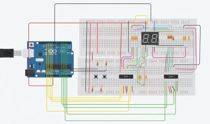
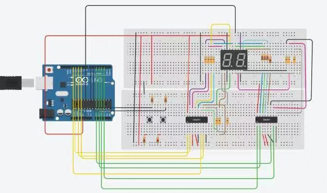
Two BCD display paths in the report两条 BCD 显示链的报告示意图
The report written by my teammates fans an Arduino Uno into two decoder/display branches and places two switches alongside them. It records the system topology; the breadboard I built and integrated used an Arduino Nano.组员撰写的作业报告从 Arduino Uno 分出两路译码/显示支路,并在旁边接入两个开关。它记录的是系统拓扑;我实际联调的面包板使用 Arduino Nano。
Project source · Digital counter项目来源 · Arduino 数码管计数器- Video视频06.02Video视频
The 17-second clip only captured changing digits只留下数字变化的 17 秒现场视频
The clip only shows both digits changing while the Arduino Nano remains powered; it does not capture a button press. Pause and reset passed the classroom demonstration, but this video cannot serve as visual evidence for them.镜头只拍到了 Arduino Nano 上电后两位数字持续变化,没有拍下按键操作。暂停和复位最终通过了课堂演示,但不能拿这段视频充当它们的影像证据。
Project source · Digital counter项目来源 · Arduino 数码管计数器 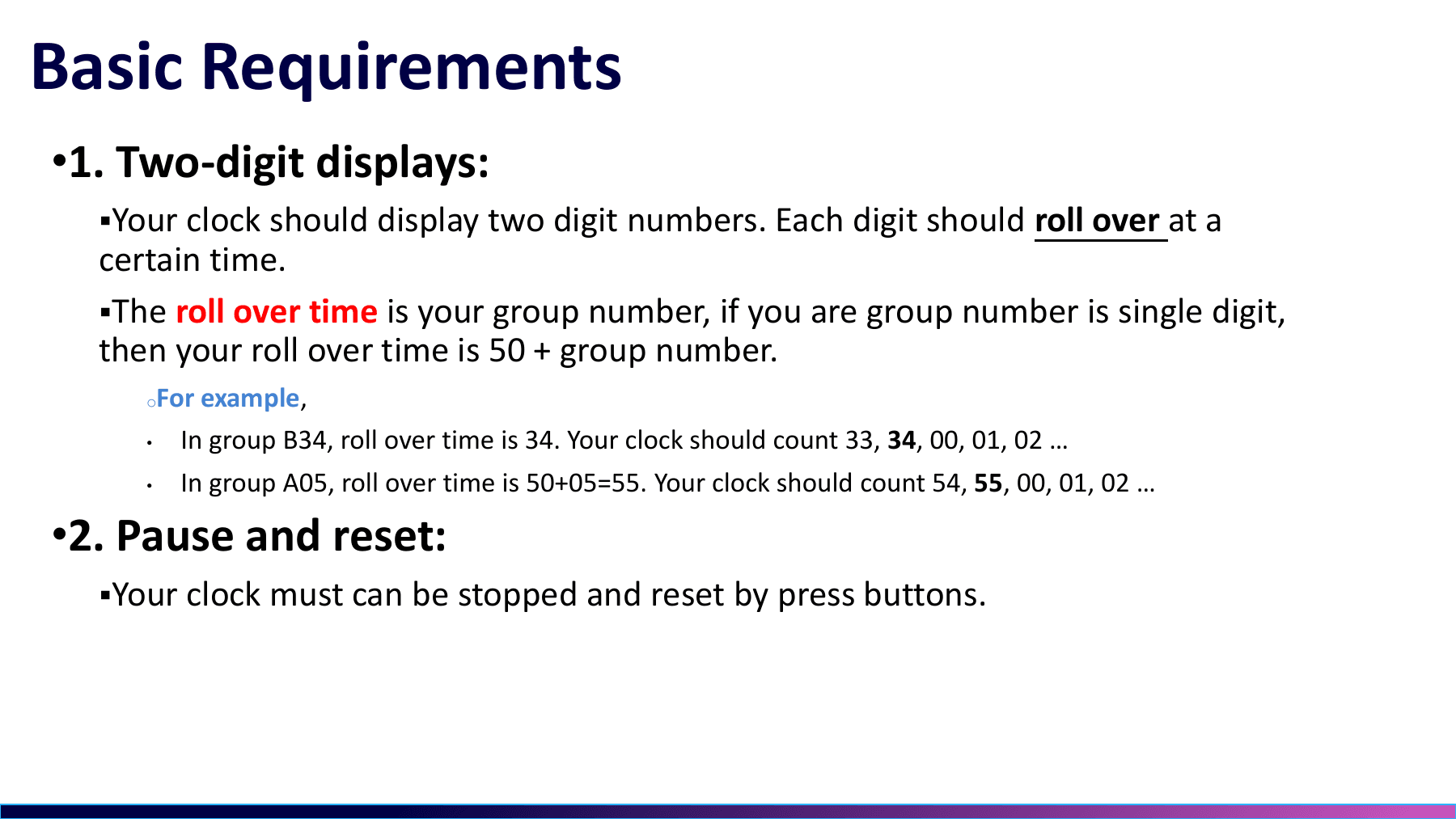 06.03Image图像
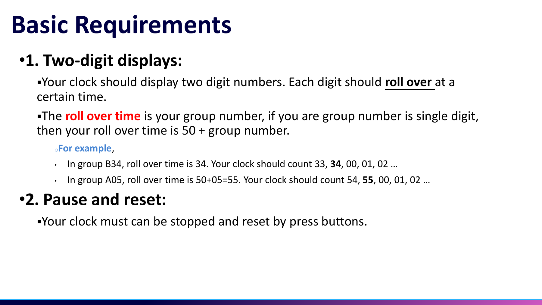
A17 rollover, pause, and reset requirementsA17 归零、暂停与复位要求
This slide defines the group-number build with two digits, rollover after 17, plus pause and reset. Counting through 99 was a separate version that I produced by changing the threshold, then flashed and demonstrated independently.这页课件定义了小组号版本,两位显示,到 17 后归零,并支持暂停和复位。计数到 99 再归零是另一个改完阈值后单独烧录、单独验证的版本。
Project source · Digital counter项目来源 · Arduino 数码管计数器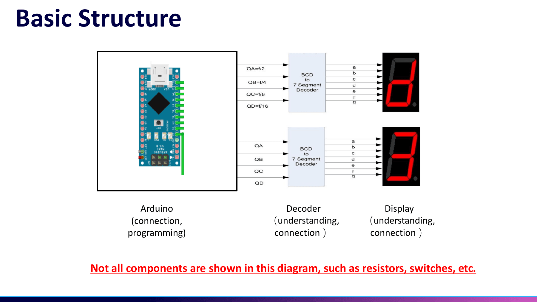 06.04Image图像
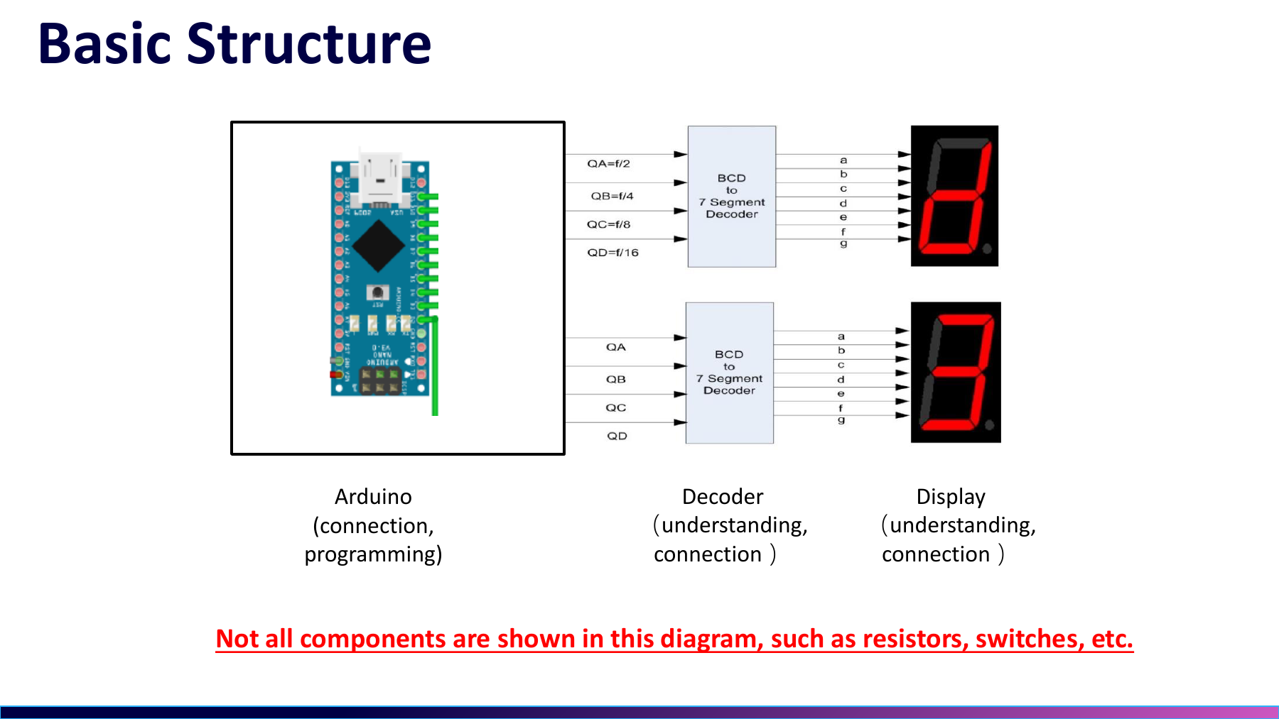
The three-stage display path I only understood later我后来才看懂的三段显示链路
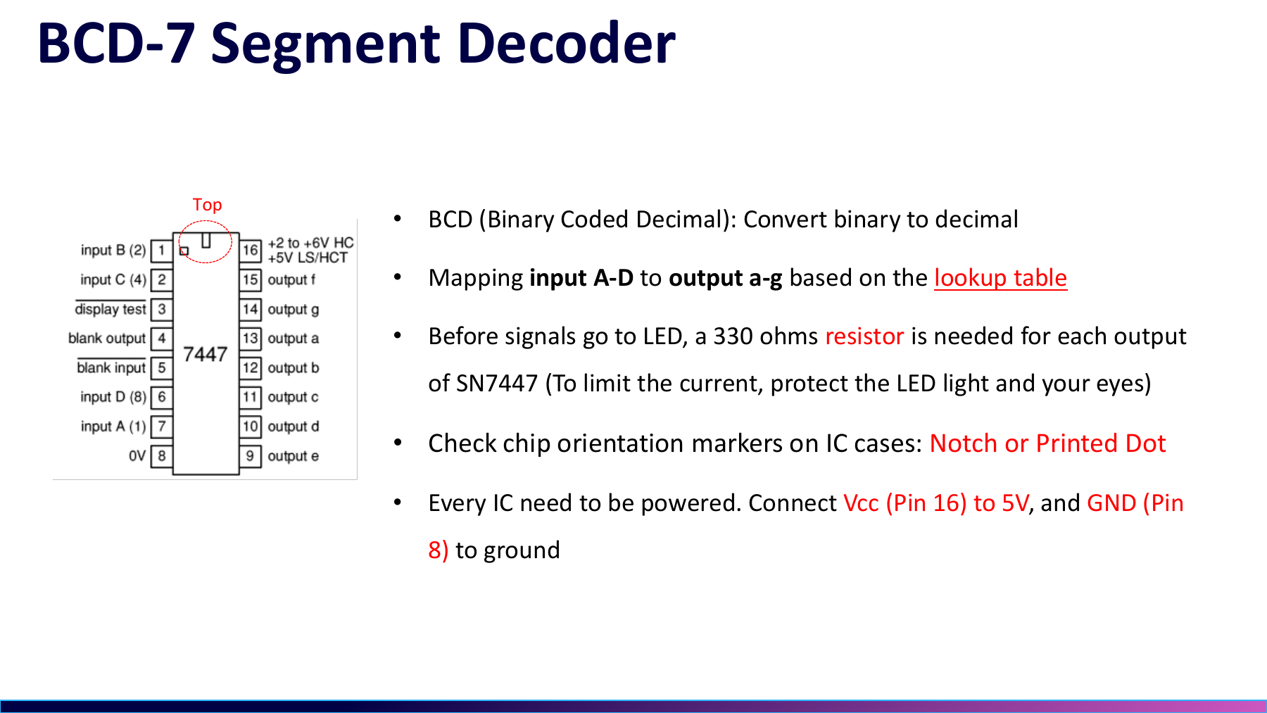
The slide reduces the system to Arduino, BCD decoder, and seven-segment display. During the project I was connecting those stages one at a time; only later did I join software state, decoder outputs, and LED current into one explanation.课件把系统压成 Arduino、BCD 译码器和数码管三段。项目当时我只是在逐段接通;现在回看,才真正把软件状态、译码输出和 LED 电流路径连成一条链。
Project source · Digital counter项目来源 · Arduino 数码管计数器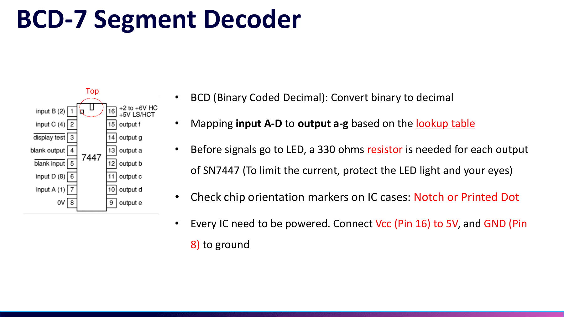 06.05Image图像
BCD logic does not define the current directionBCD 逻辑之外,还有电流方向
The slide marks A-D inputs, a-g outputs, power, and segment resistors around a 7447-style device. Four BCD bits select a number; whether it lights still depends on output polarity, the display common, and the actual current path.这页标出了 7447 类器件的 A-D 输入、a-g 输出、供电和段限流。四位 BCD 只决定数字;显示能否点亮,还取决于驱动极性、公共端和实际电流路径。
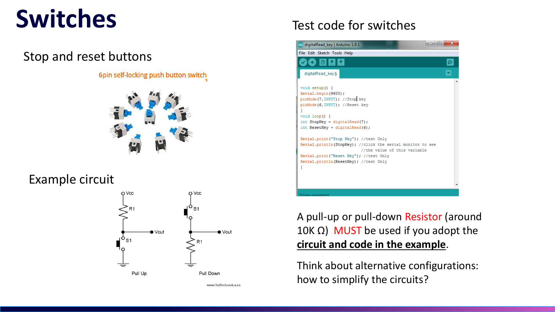
Project source · Digital counter项目来源 · Arduino 数码管计数器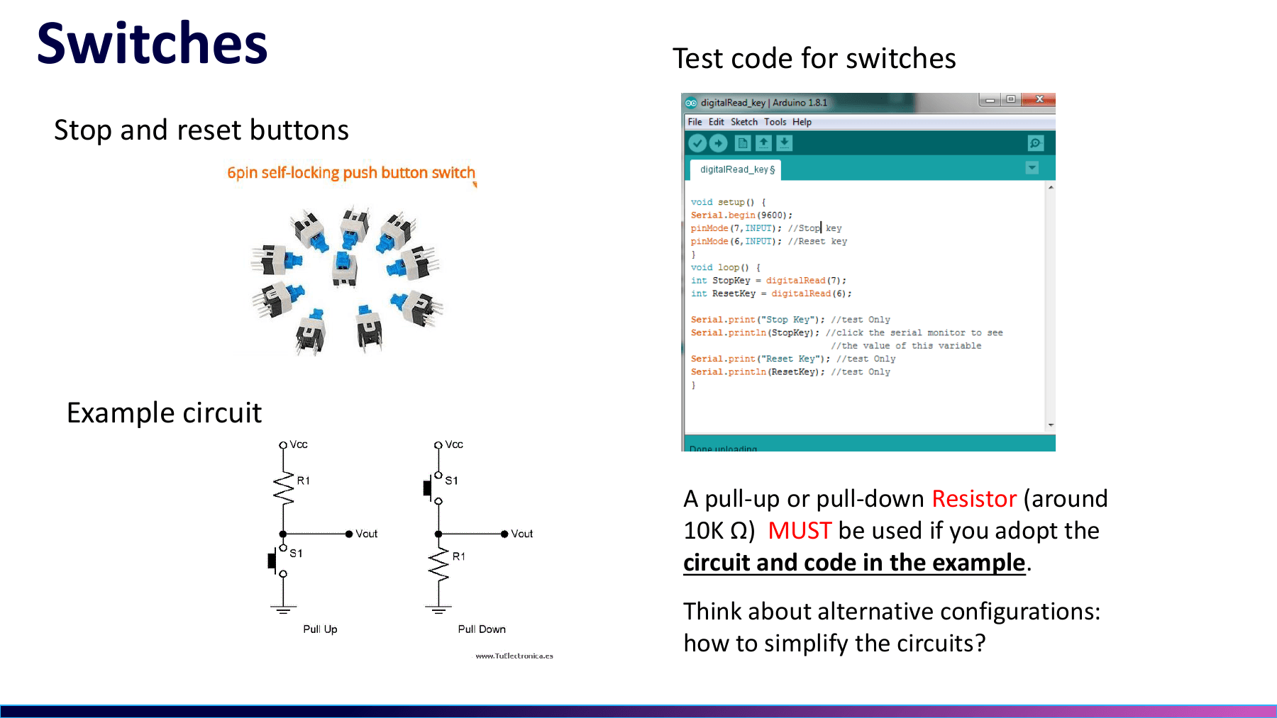 06.06Image图像
A six-pin switch mapped with a multimeter靠万用表摸清的六脚按键
Without a matching datasheet, the six pins produced no response, unstable readings, and repeated triggers. I borrowed a multimeter and checked continuity pair by pair before reconnecting the pause and reset functions.没有对应数据手册时,六只脚让我遇到没反应、乱跳和重复触发。我借来万用表逐对测通断,先确认按下前后的内部连接,再把暂停和复位接回程序。
Project source · Digital counter项目来源 · Arduino 数码管计数器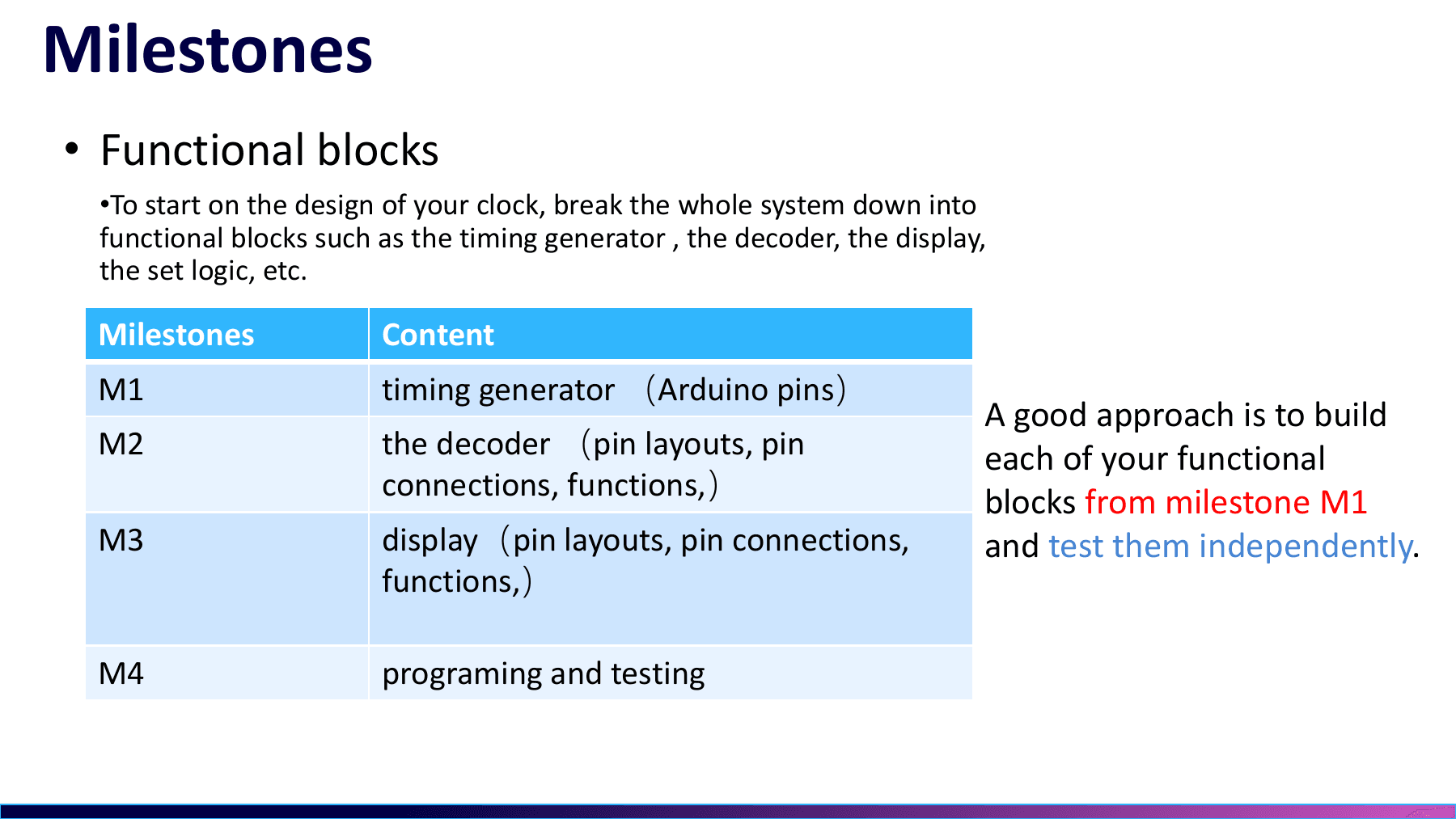 06.07Image图像
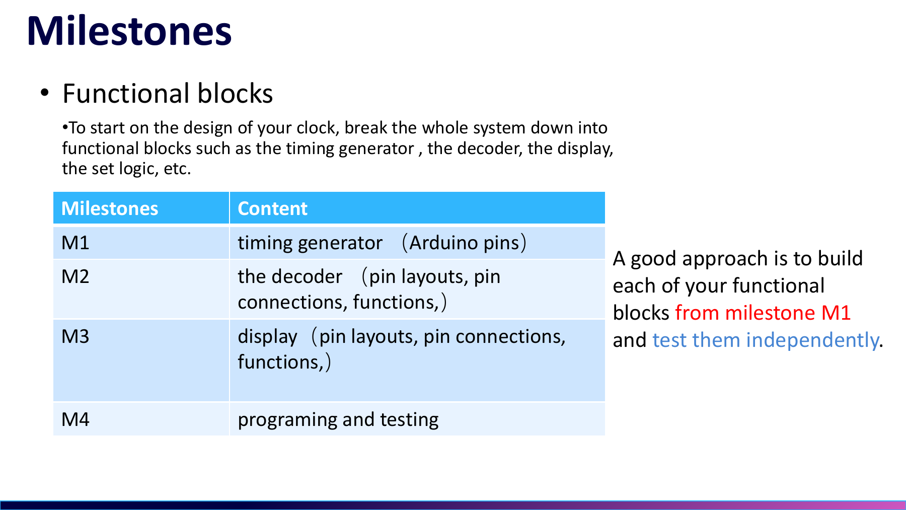
From a one-digit demo to two-digit integration从一位 demo 到两位联调
Development roughly followed the course sequence. I read the material, ran a one-digit BCD example, wired two digits, split units and tens, added the buttons, then integrated the system. The two demo sketches were early checkpoints, not the final program.实际开发大致沿着课件顺序推进。我先读资料和跑一位 BCD 示例,再铺两位接线、拆分个位与十位、加入按键,最后联调。两份 demo sketch 都只是前期检查点。
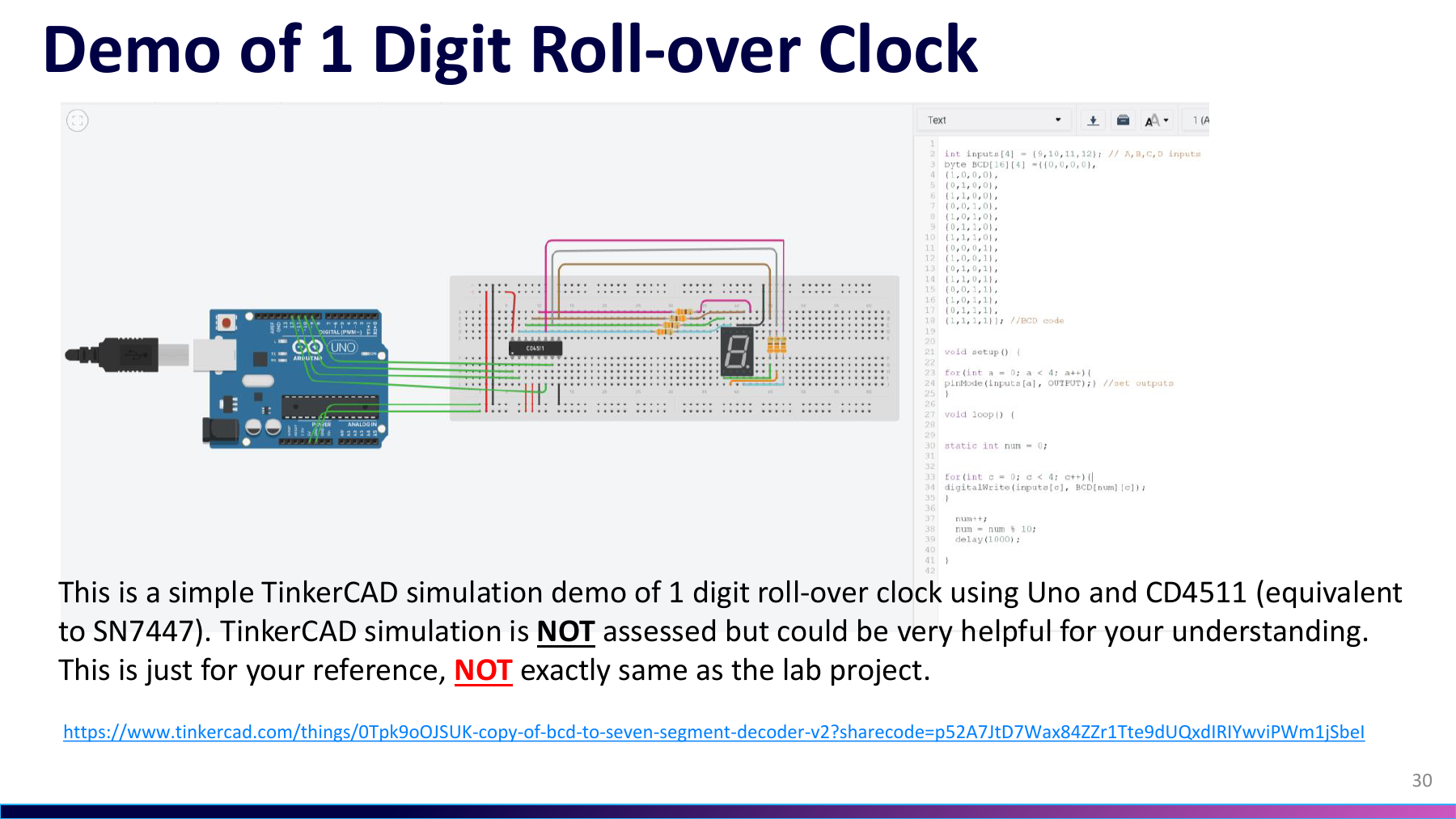
Project source · Digital counter项目来源 · Arduino 数码管计数器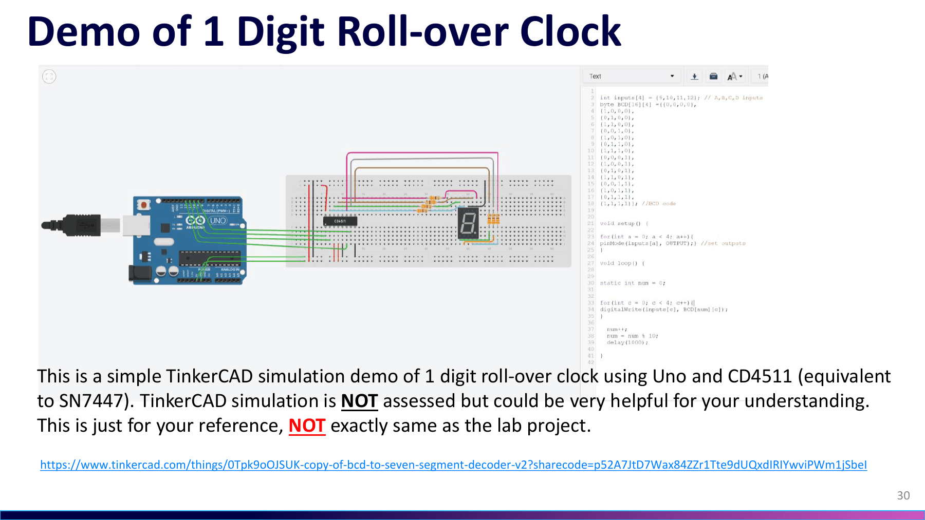 06.08Image图像
The CD4511 simulation omitted a polarity assumption漏掉极性前提的 CD4511 仿真
TinkerCAD uses a CD4511 to drive a common-cathode display, while the physical LS47 path was intended for common-anode operation. Both decode BCD, but they cannot use the same common-pin connection; that mismatch produced the dark or scrambled display.TinkerCAD 用 CD4511 驱动共阴数码管,实物的 LS47 路径却面向共阳显示。两者都做 BCD 译码,但不能共用同一个公共端接法;这正是当时不亮/乱码故障的来源。
Project source · Digital counter项目来源 · Arduino 数码管计数器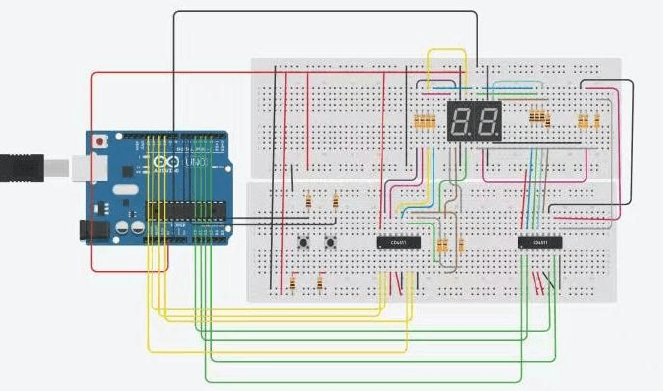 06.09Image图像
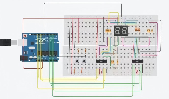
Two decoder branches in the A17 reportA17 报告中的双译码支路
The cropped report places two decoders between an Arduino Uno and two displays, with resistors and switches nearby. It captures the intended branch relationship; the circuit I built and integrated on the bench used an Arduino Nano.报告裁图把两颗译码器放在 Arduino Uno 与两位数码管之间,旁边还有电阻和开关。它说明了预期支路关系;我实际搭建和联调的是 Nano 面包板版本。
Project source · Digital counter项目来源 · Arduino 数码管计数器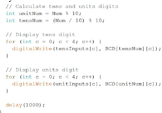 06.10Image图像
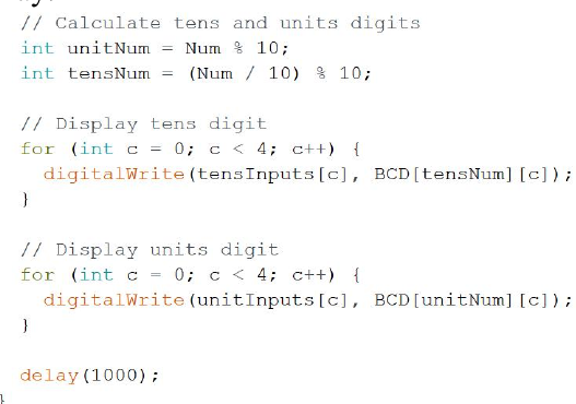
How one state becomes units and tens一个状态怎样拆成个位和十位
`Num % 10` extracts units and `(Num / 10) % 10` extracts tens. Each result selects a four-bit BCD row for its own decoder; this was the two-digit split I learned while building the project.`Num % 10` 取个位,`(Num / 10) % 10` 取十位;两个结果各自查一行四位 BCD,再送进两颗译码器。这是我当时边查资料边学会的两位显示拆分。
Project source · Digital counter项目来源 · Arduino 数码管计数器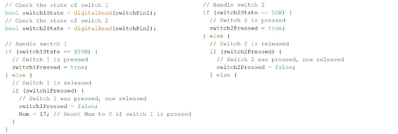 06.11Image图像
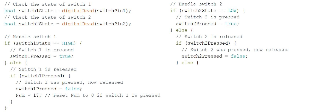
A button screenshot that cannot settle the final wiring无法替最终硬件下结论的按键截图
The excerpt checks switch 1 with HIGH and switch 2 with LOW, while the report also mentions a pull-up. Both buttons passed the classroom demonstration, but without the final wiring and source this image cannot prove a tidy polarity or debounce implementation.截图里 switch 1 用 HIGH,switch 2 用 LOW,报告文字还提到上拉。最终两个按键确实通过了课堂演示,但缺少最终源码与接线,不能据此补出一套整齐的极性或消抖实现。
Project source · Digital counter项目来源 · Arduino 数码管计数器
Arduino Smart Car Line-Tracking KitArduino 循迹小车焊接与控制实训
I assembled and tested an Arduino car kit, learned to trace its power, sensing, and motor circuits, and helped tune the team’s car to a top-5-percent finish in the campus lap-speed challenge.我从裸 PCB 开始装配 Arduino 小车,逐项检查电源、传感和电机功能,再参与赛道调试;小组最终进入校内圈速挑战前 5%。
- Records记录
- 012
- Images图像
- 012
- Videos视频
- 000
 07.01Image图像
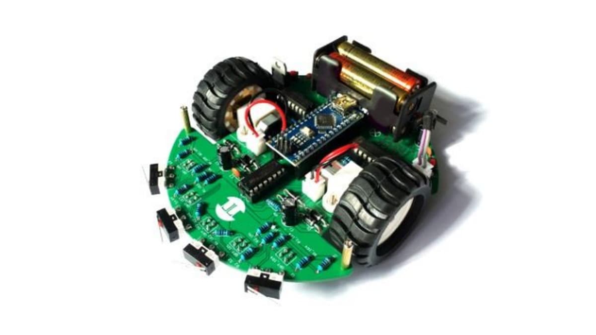
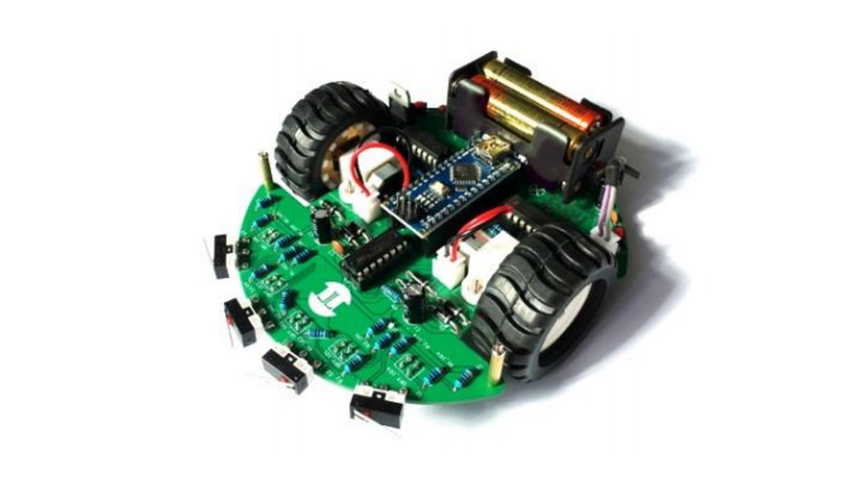
Course Reference Smart-Car Assembly课程参考车装配示意
The green reference car shows the kit's intended layout with a Nano-format controller, two driven wheels, a battery holder, and front collision arms. It is not the purple build documented in this project.绿色参考车展示套件的预期布局,包括 Nano 尺寸控制板、两只驱动轮、电池盒和前缘碰撞拨杆;它并非本项目记录的紫色实物。
Project source · Line-tracking car项目来源 · Arduino 循迹小车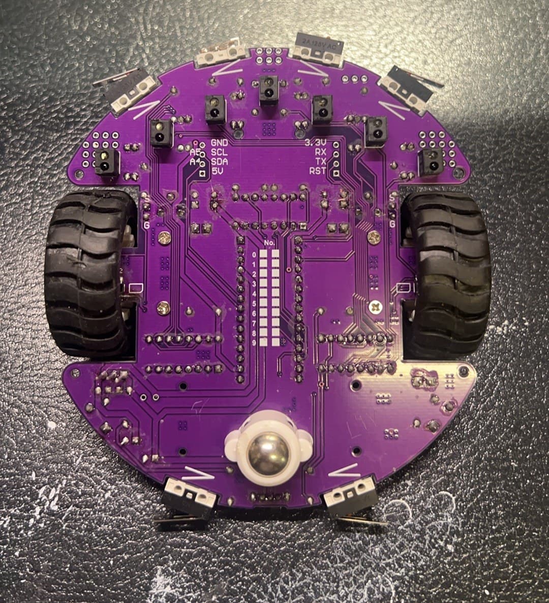 07.02Image图像
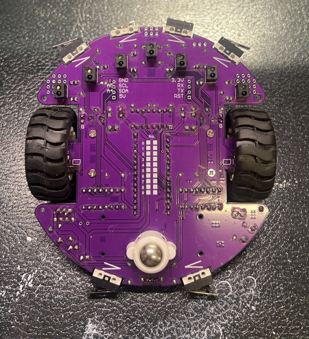
Purple Chassis From Below紫色小车底面
The underside of the assembled purple chassis exposes the through-hole joints, six downward-facing IR tracking sensors, two drive wheels, ball caster, and long-arm collision switches around the edge.装配后的紫色底盘翻到背面,通孔焊点、六个朝下的红外循迹传感器、两只驱动轮、滚珠万向轮和沿板边布置的长臂碰撞开关都直接可见。
Project source · Line-tracking car项目来源 · Arduino 循迹小车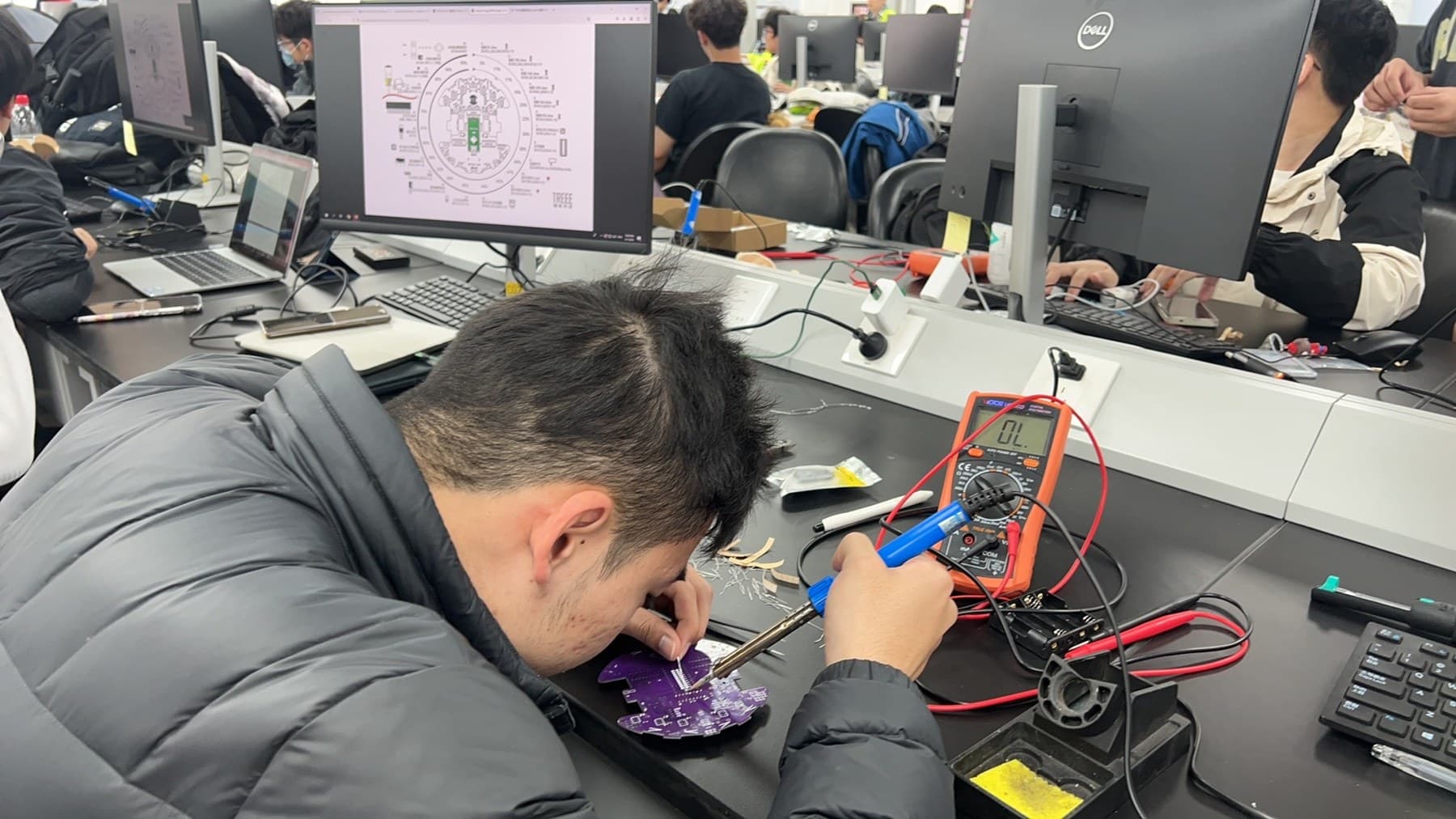 07.03Image图像
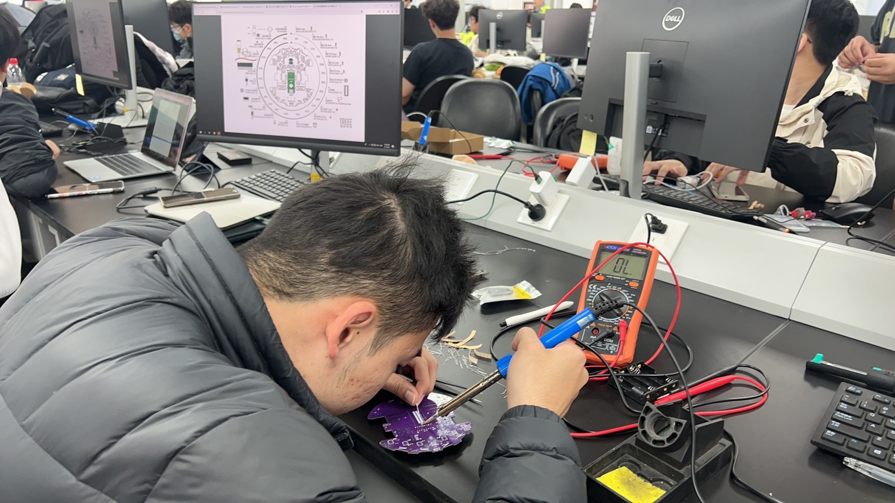
Populating the Purple PCB at the Bench在焊台上装配紫色 PCB
The assembly record catches the board mid-solder, with its circular parts map open on the monitor and a multimeter beside the iron.装配记录停在焊接进行时。显示器上打开圆形元件布局图,电烙铁旁放着万用表。
Project source · Line-tracking car项目来源 · Arduino 循迹小车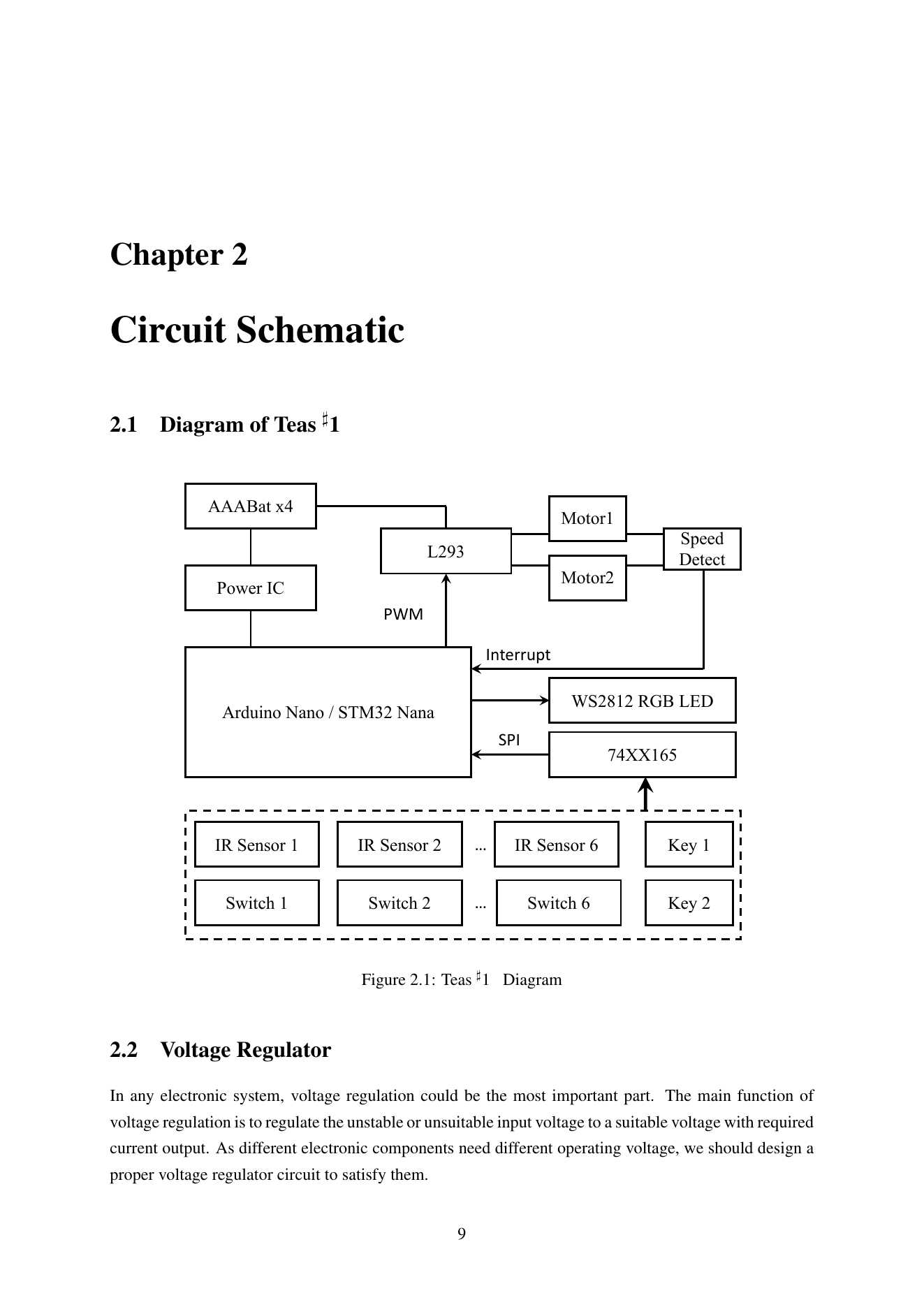 07.04Image图像
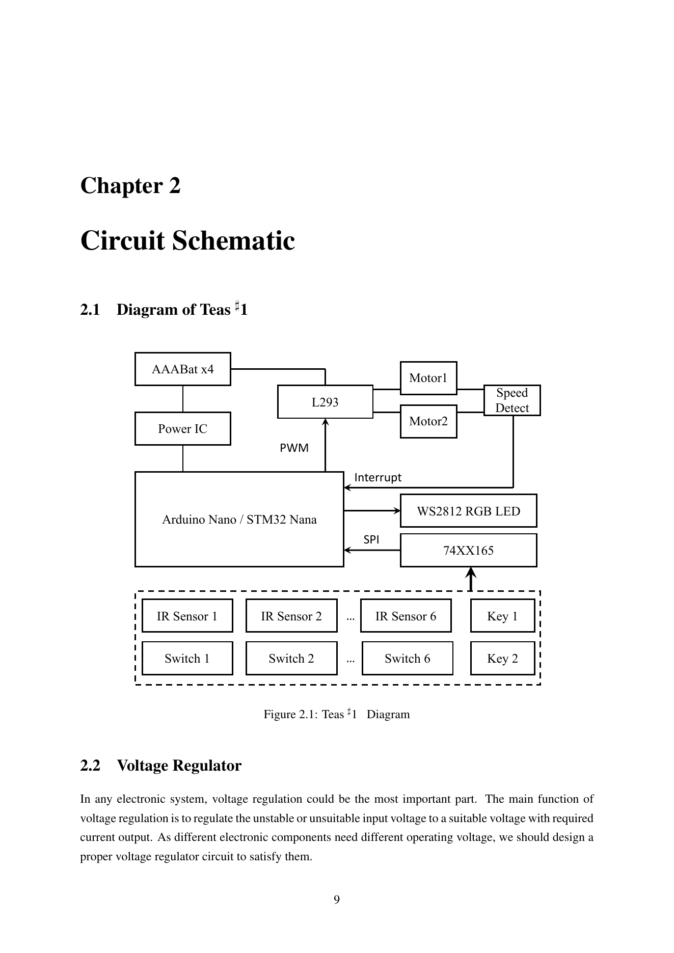
Power, Inputs, and Motion in One Diagram一张图串起电源、输入与运动
The manual connects four AAA cells through a power IC to the controller, routes PWM through L293 to two motors, and returns six IR inputs, six switches, and two keys through 74XX165.手册把四节 AAA 电池经电源芯片接到控制器,再让 PWM 经 L293 驱动双电机;六路红外、六个开关和两个按键则通过 74XX165 返回主控。
Project source · Line-tracking car项目来源 · Arduino 循迹小车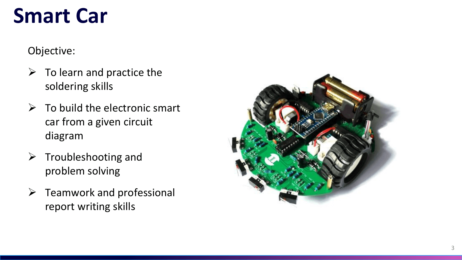 07.05Image图像
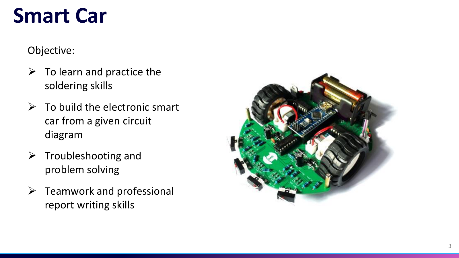
From Soldering to Troubleshooting从焊接走到故障排查
The course frame separates four aims. These were to practise soldering, build the car from the given circuit, troubleshoot problems, and work as a team while writing a professional report.课程把目标拆成四项。练习焊接,按给定电路完成小车装配,开展故障排查与问题解决,并以团队协作完成专业报告。
Project source · Line-tracking car项目来源 · Arduino 循迹小车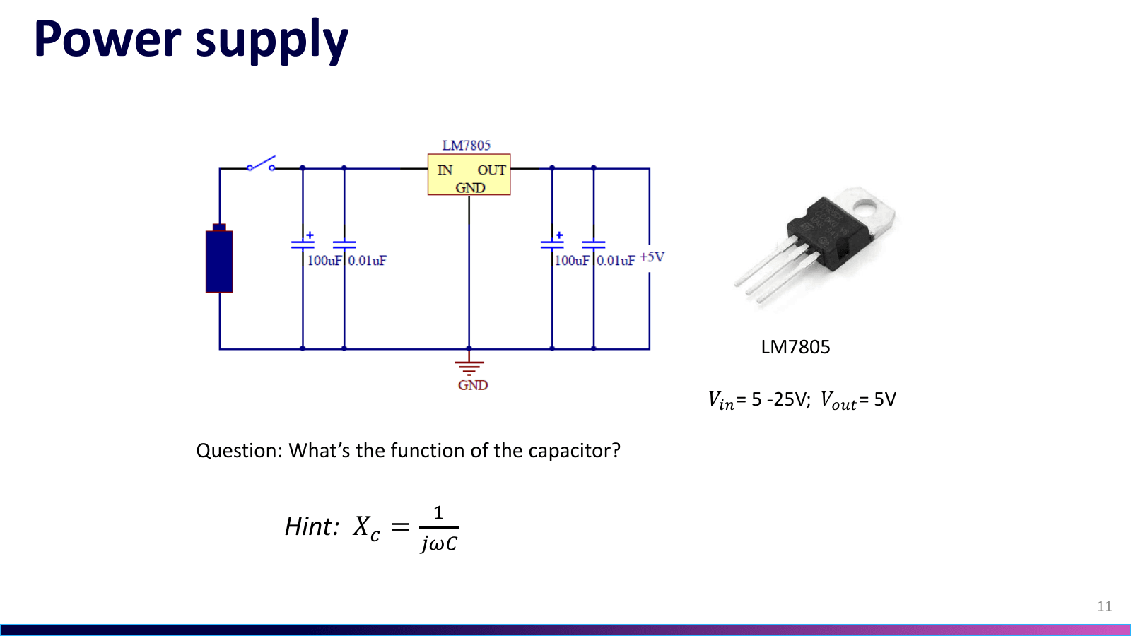 07.06Image图像
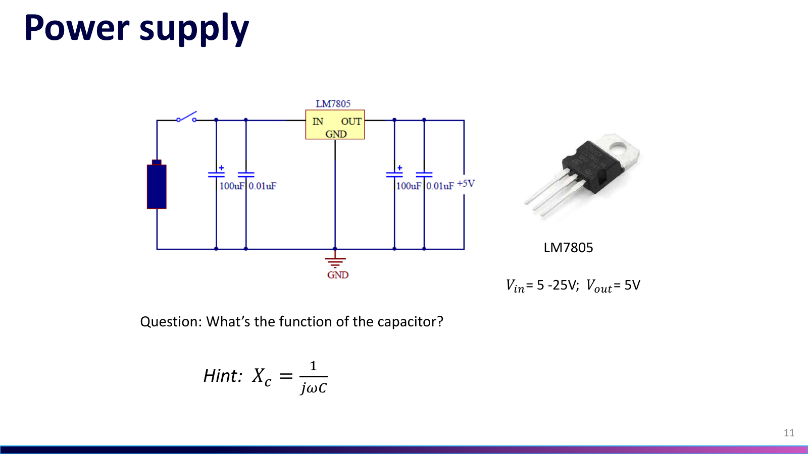
LM7805 Sets the 5 V RailLM7805 建立 5 V 电源轨
The course slide's schematic places 100 µF and 0.01 µF capacitors on both sides of the LM7805 and labels a 5 V output, linking the regulator stage to supply filtering.课件页原理图在 LM7805 输入、输出两侧各放置 100 µF 与 0.01 µF 电容,并标出 5 V 输出,把稳压级与电源滤波联系起来。
Project source · Line-tracking car项目来源 · Arduino 循迹小车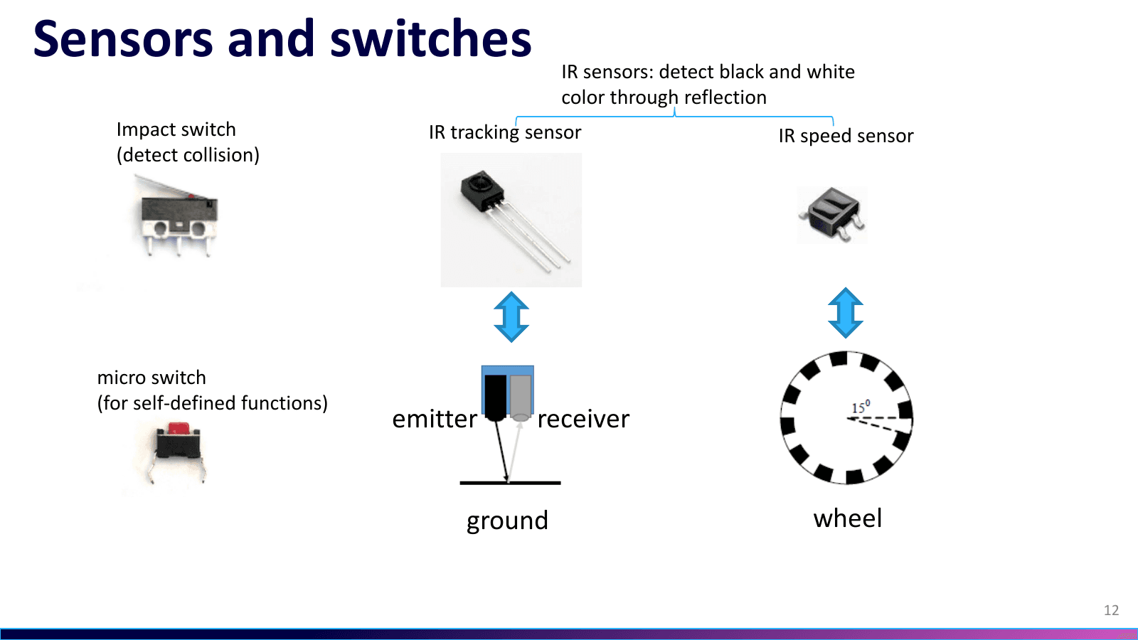 07.07Image图像
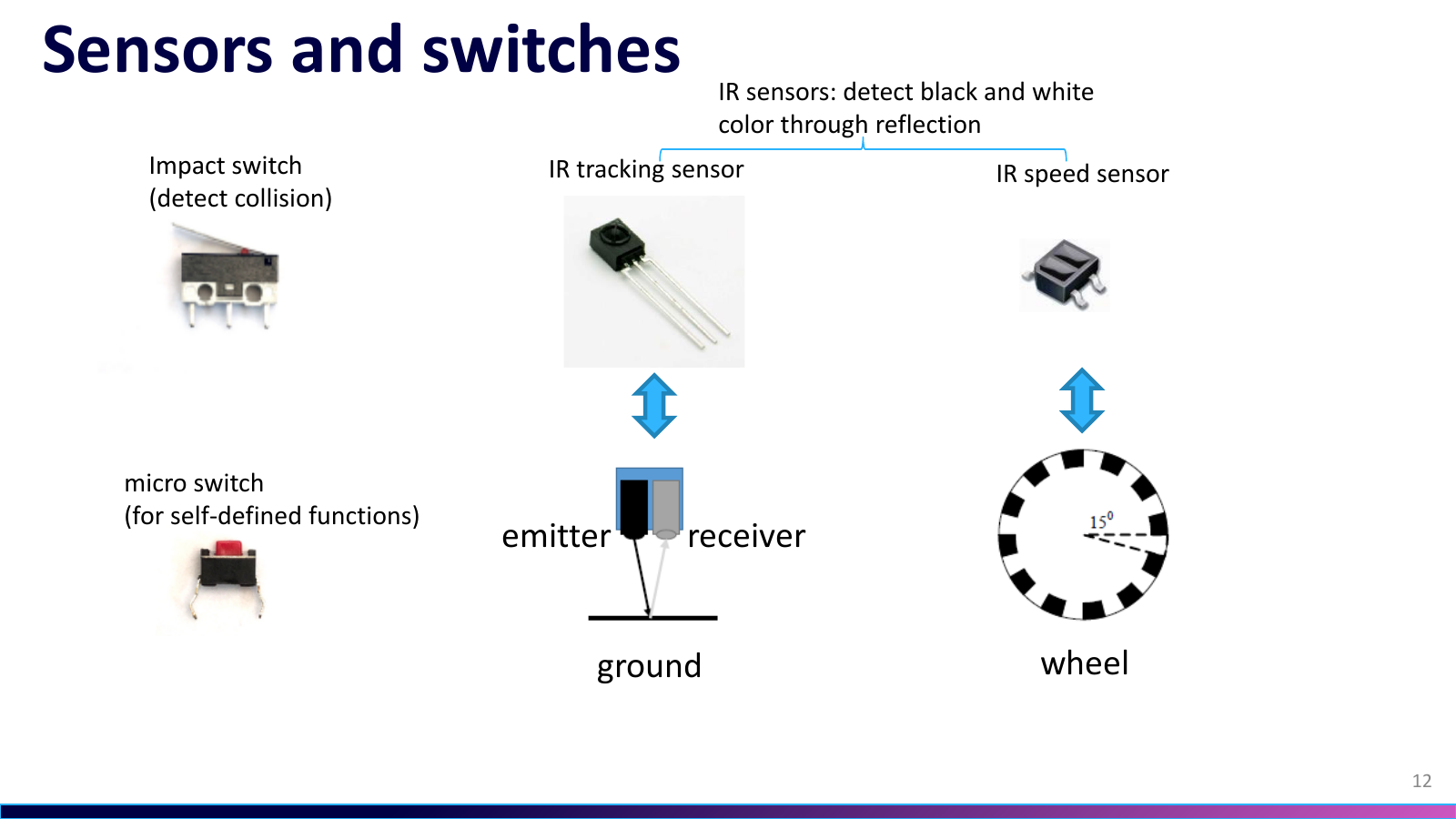
Reflection, Collision, and Wheel Speed反射、碰撞与轮速
The course slide separates contact inputs from optical ones. An impact switch and a key provide contact inputs, an emitter-receiver pair tracks black and white, and an IR speed sensor reads a striped wheel.课件页把接触输入与光学输入分开。碰撞开关与按键负责触发,收发一体的红外对管辨别黑白,条纹轮盘则由红外测速传感器读取。
Project source · Line-tracking car项目来源 · Arduino 循迹小车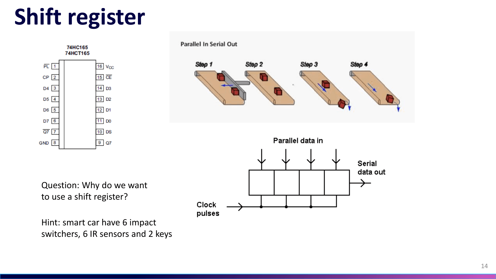 07.08Image图像
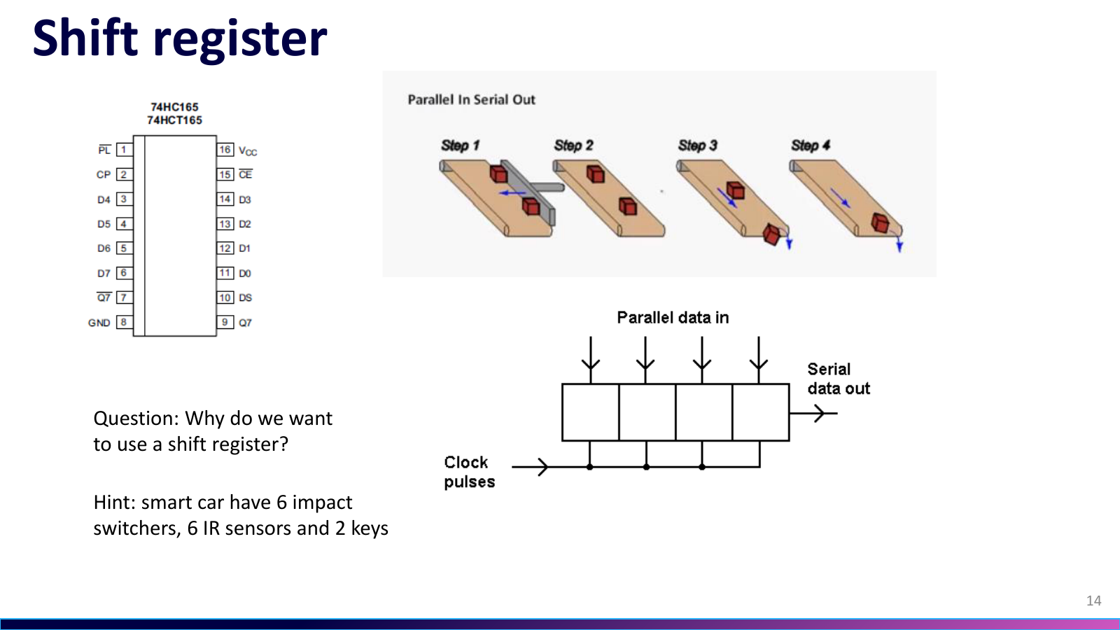
Fourteen Inputs, One Serial Read Path十四路输入,一条串行读取路径
The course slide counts six collision switches, six IR channels, and two keys as fourteen inputs; its parallel-in/serial-out model explains why the kit cascades two 74HC165s before the controller.课件页把六个碰撞开关、六路红外和两个按键合计为十四路输入;并入串出的模型解释了套件为何在主控前级联两颗 74HC165。
Project source · Line-tracking car项目来源 · Arduino 循迹小车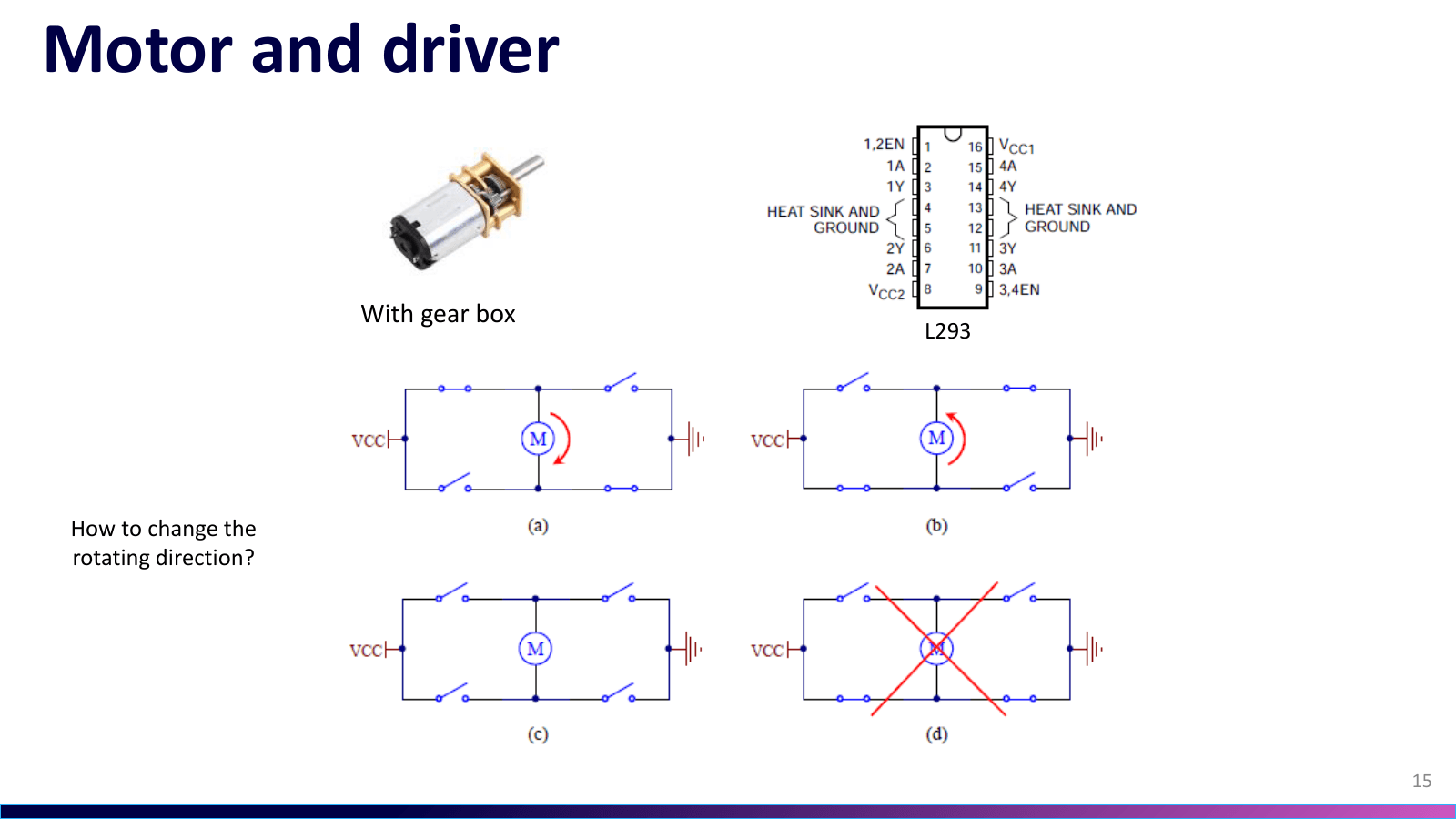 07.09Image图像
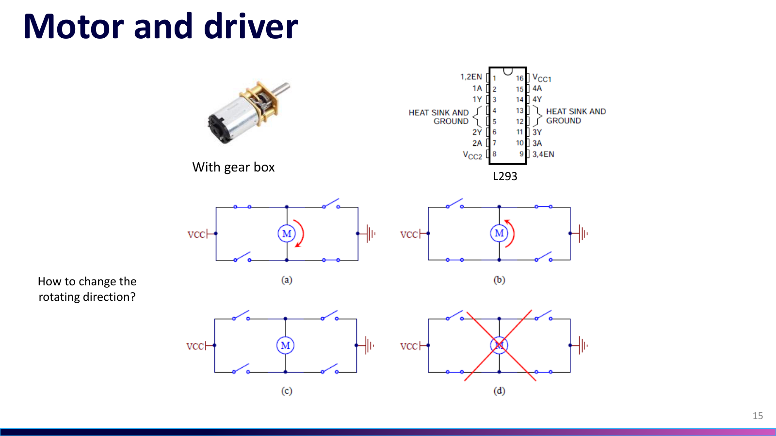
L293 Reverses the Geared MotorsL293 让减速电机正反转
On the course slide, the H-bridge sketches show how reversing the applied polarity changes motor direction; L293 packages that drive stage between the controller and two geared motors.课件页中的 H 桥示意图说明反转施加极性会改变电机方向;L293 把这一级驱动封装在控制器与两只减速电机之间。
Project source · Line-tracking car项目来源 · Arduino 循迹小车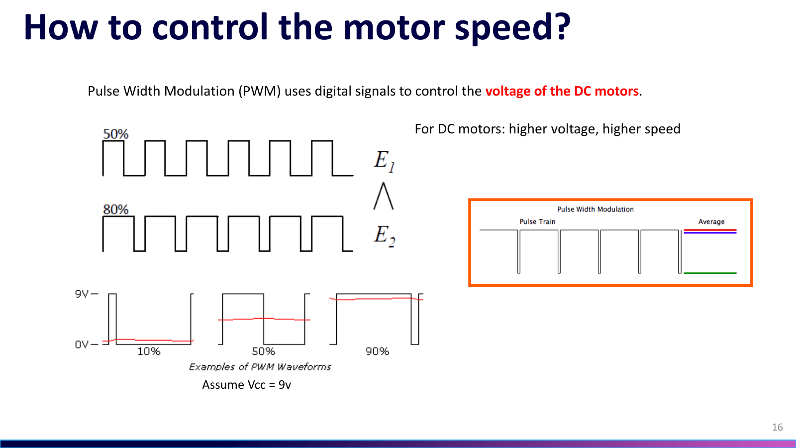 07.10Image图像
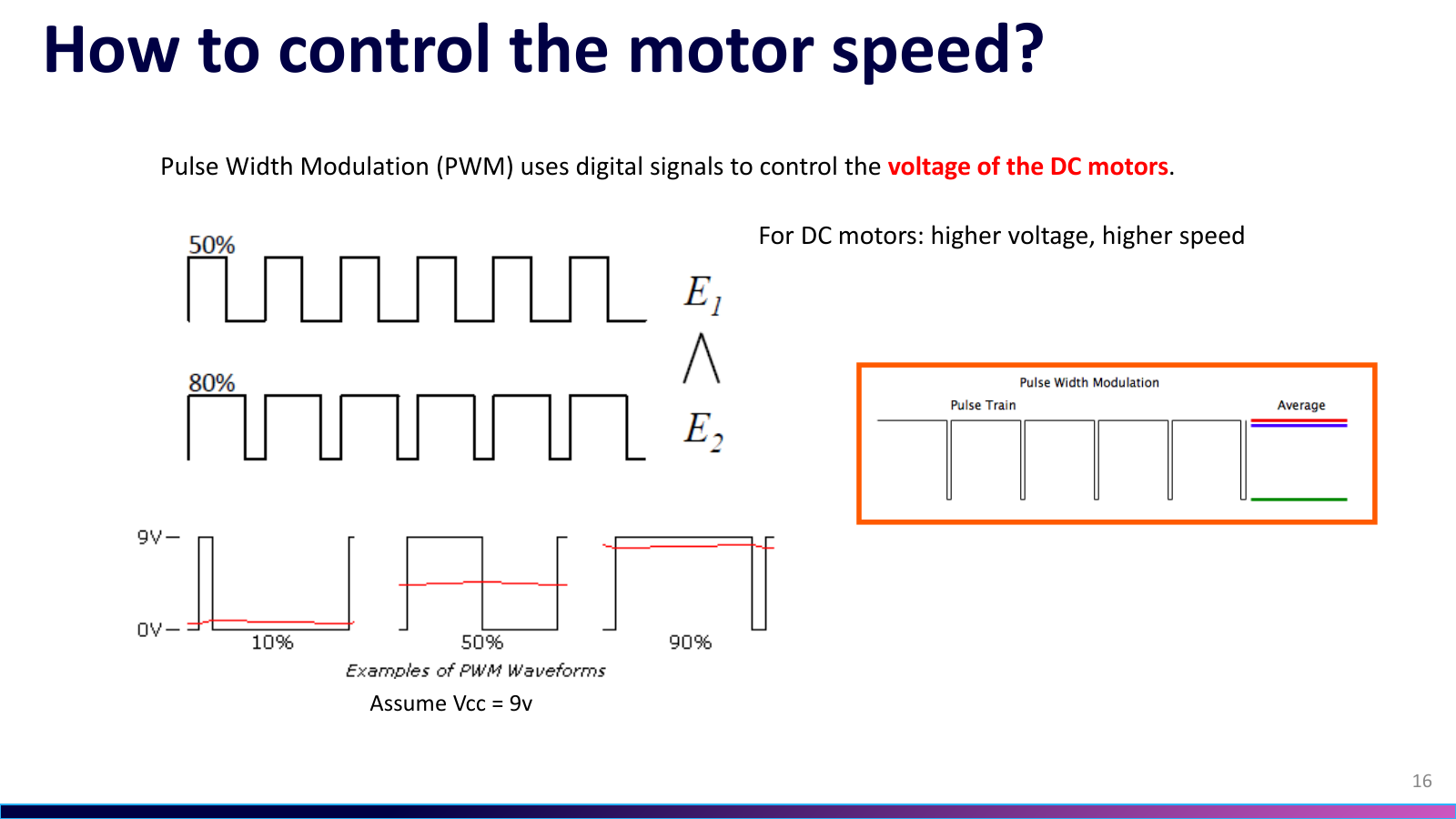
Duty Cycle Sets Average Motor Drive占空比设定电机平均驱动
The course slide's 50% and 80% pulse trains, plus 10/50/90% examples, show how duty cycle changes the average drive applied to a motor; the project code then adjusts the left- and right-wheel PWM commands separately.课件页用 50% 与 80% 脉冲列和 10/50/90% 示例说明占空比如何改变施加到电机的平均驱动;项目代码随后分别调整左右轮的 PWM 指令。
Project source · Line-tracking car项目来源 · Arduino 循迹小车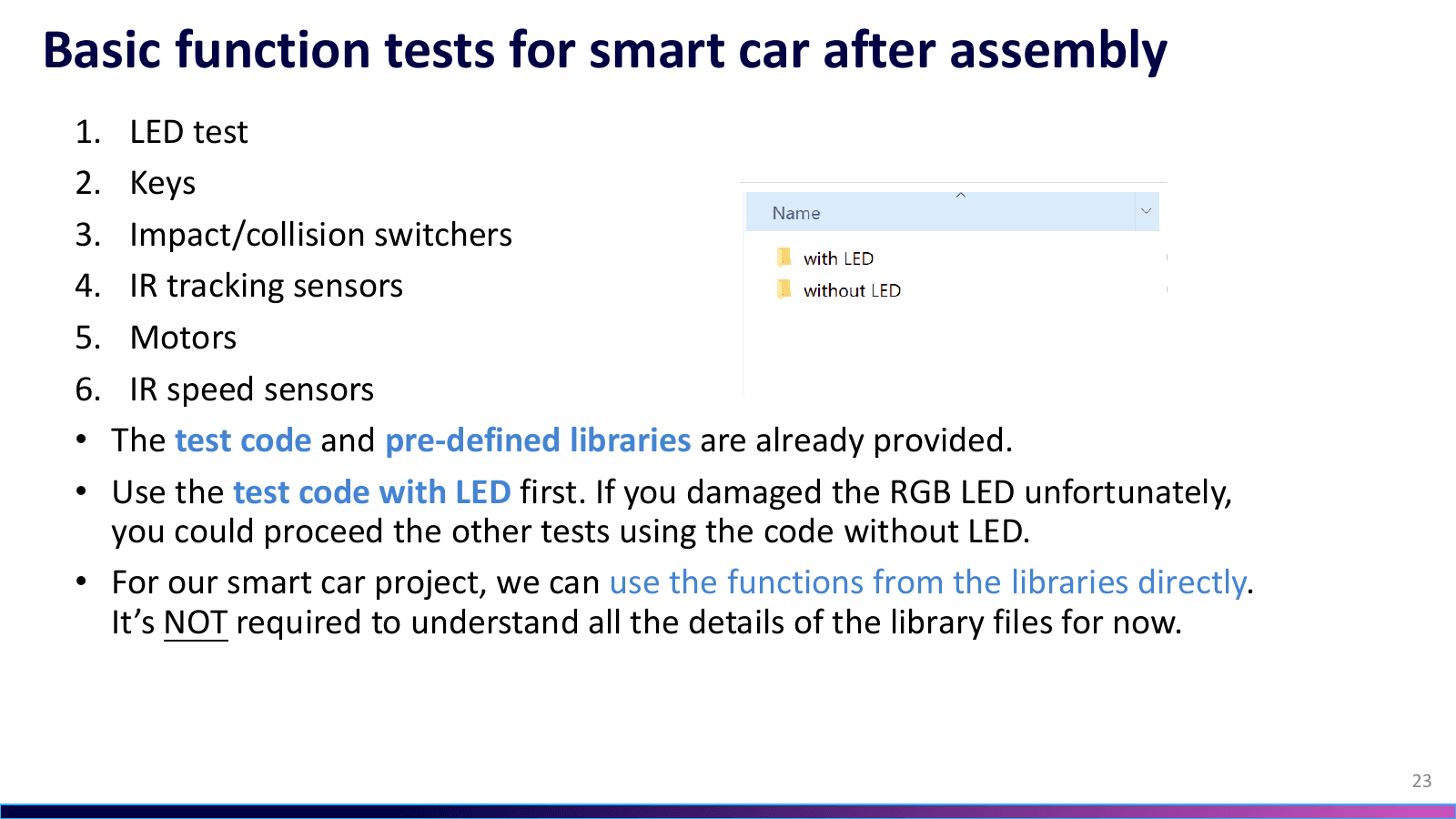 07.11Image图像
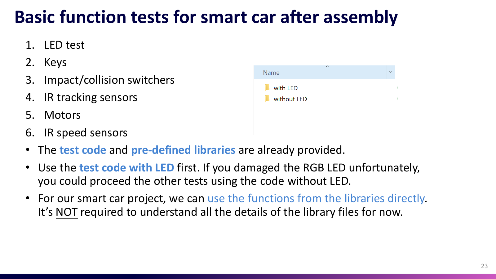
Six Tests Before Full Line Tracking完整循迹前的六项测试
The course slide prescribes separate checks for LED, keys, collision switches, IR tracking channels, motors, and IR speed sensing; the supplied code also offered variants with and without the RGB LED.课件页规定逐项检查 LED、按键、碰撞开关、红外循迹通道、电机和红外测速;配套代码还提供带 RGB LED 与不带 LED 两种版本。
Project source · Line-tracking car项目来源 · Arduino 循迹小车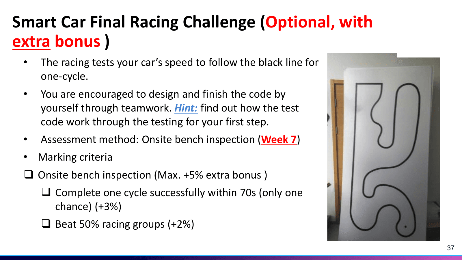 07.12Image图像
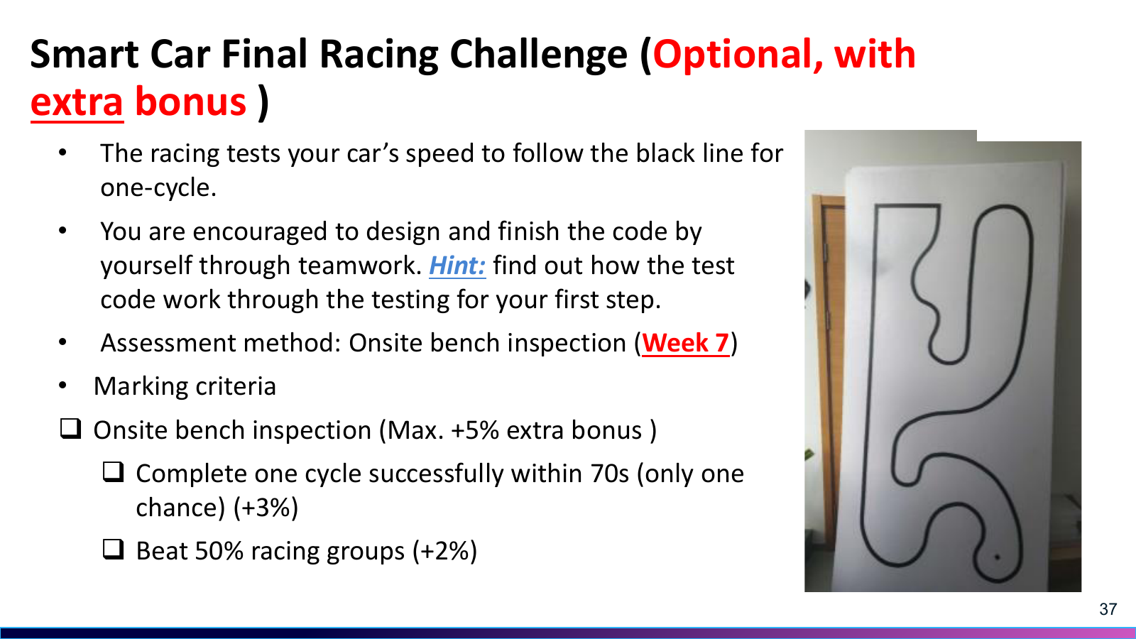
One Lap Brings the Signal Chain Together一圈赛道把整条链路接起来
The optional course slide asks the car to follow one black-line lap, awarding a 3% bonus within 70 s and another 2% for beating half the groups; the project record later reports a top-5% finish.可选挑战课件页要求小车沿黑线跑完一圈。70 秒内完成可获 3% 额外加分,超过半数小组再获 2%;项目记录显示这台车最终进入圈速前 5%。
Project source · Line-tracking car项目来源 · Arduino 循迹小车
Claude Chime Power BoardClaude Chime 电源板
For an independent hardware commission from Accele AI, I designed and hand-assembled Claude Chime's ESP32 peripheral power board. The roughly 28 × 27 mm PCB combines single-cell charging, two separate boost rails, gated battery-voltage sensing, and a 5 V push-pull solenoid driver. I completed basic power-up and interface checks; the client's firmware engineer later reported normal complete-device operation.受 Accele AI 委托,我独立设计并手工焊接了 Claude Chime 的 ESP32 外围电源板。约 28 × 27 mm 的 PCB 集成单节锂电池充电、两路独立升压、受控电池电压采样和 5 V 推拉式电磁铁驱动。我完成了基础上电与接口测试,客户固件工程师随后反馈整机运行正常。
- Records记录
- 001
- Images图像
- 001
- Videos视频
- 000