

Custom Driver Board and Sensorless FOC自制驱动板与无感 FOC 实践
I designed and assembled an STM32F446/DRV8301 driver, adapted open-source firmware, and ran a compressor on a 12 V bus with 30 to 80 Hz open-loop commands. Sensorless handoff remains unresolved.我独立设计、装配 STM32F446/DRV8301 驱动板,适配开源固件,在 12 V 母线下用 30 到 80 Hz 开环指令带动压缩机;无感接管仍未完成。
- Timeline时间线
- 2025.11 - Present2025.11 - 至今
- Status状态
- Ongoing Learning Route持续学习 / 阶段原型
- Stack技术栈
- FOCMotor ControlSTM32F4DRV8301PCBSVPWM
Building the Driver自制驱动板
After a PMSM-FOC course, I wanted to make the equations drive a real motor. I had only brushed motors nearby, no suitable three-phase brushless load, and the companion teaching board cost RMB 888. I decided to build the driver myself, gaining an experimental platform while working through the course's circuit ideas again.
学完一套 PMSM-FOC 课程后,我很想让那些公式真正带动电机。手边却只有有刷电机,没有合适的三相无刷负载,配套教学板又要 888 元。我决定先把驱动板自己做出来,一边补上实验条件,一边把课程里的电路重新弄明白。
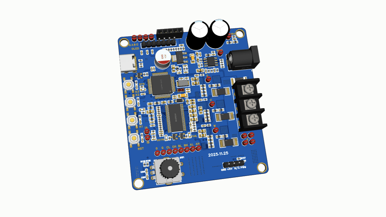
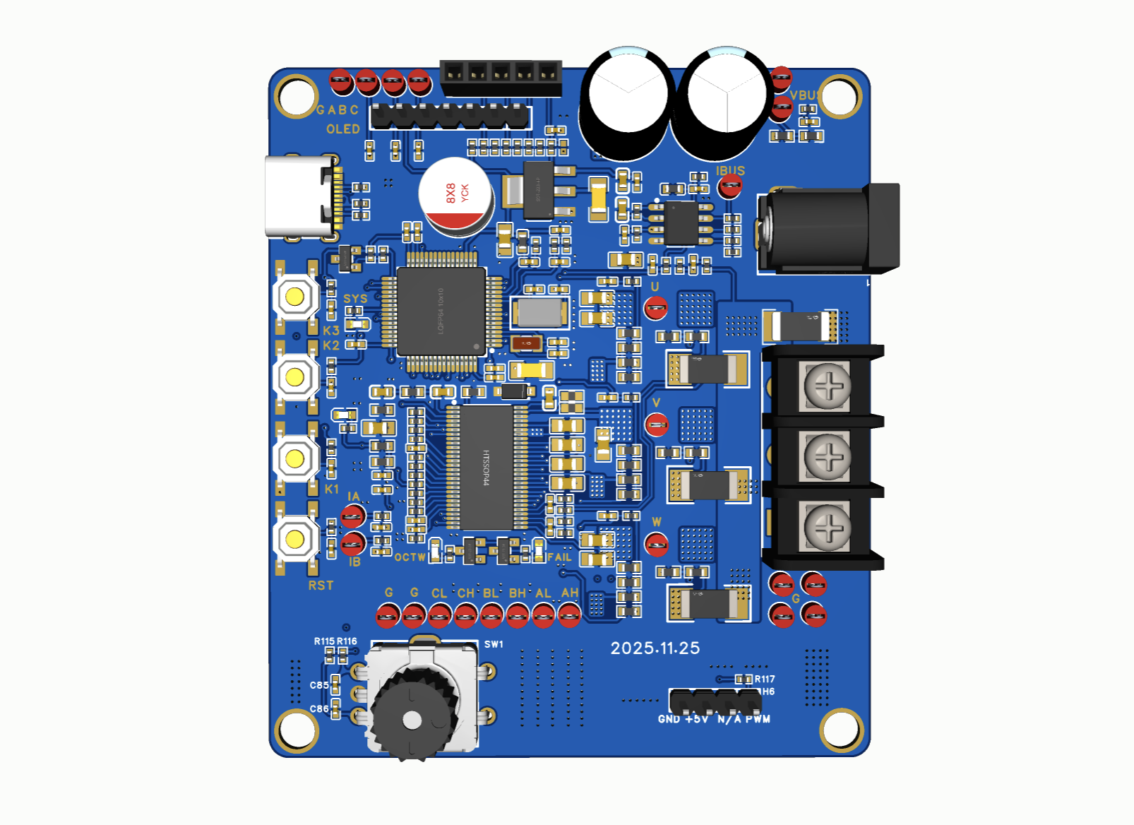
The PCB silkscreen marks 25 November 2025, the day I started drawing it. Using chip reference circuits, I independently completed the schematic, component selection, layout, and manufacturing files. The design went for fabrication in January 2026.
PCB 丝印上的 2025 年 11 月 25 日,就是我开始画板的日期。我参考芯片推荐电路,独立完成原理图、器件选型、PCB 布局与制造文件,到 2026 年 1 月完成设计并送去打板。
While I was working on another project, a small compressor arrived in the workshop. Reading its manual and following the three-phase connections showed me that its internal permanent-magnet motor could serve as the load. I had been looking for a brushless motor; the eventual experiment involved compressor startup, sustained operation, and disturbances, considerably more tangible than an ideal course model.
刚好在做另一个项目时,工作室里出现了一台小型压缩机。我查手册、沿三相接线继续了解,才知道内部的永磁电机可以作为实验负载。原先只是想找一台无刷电机,后来要面对的变成了压缩机起转、持续运行与扰动,比课程里的理想模型具体得多。
From Schematic to Hardware从原理图到实物
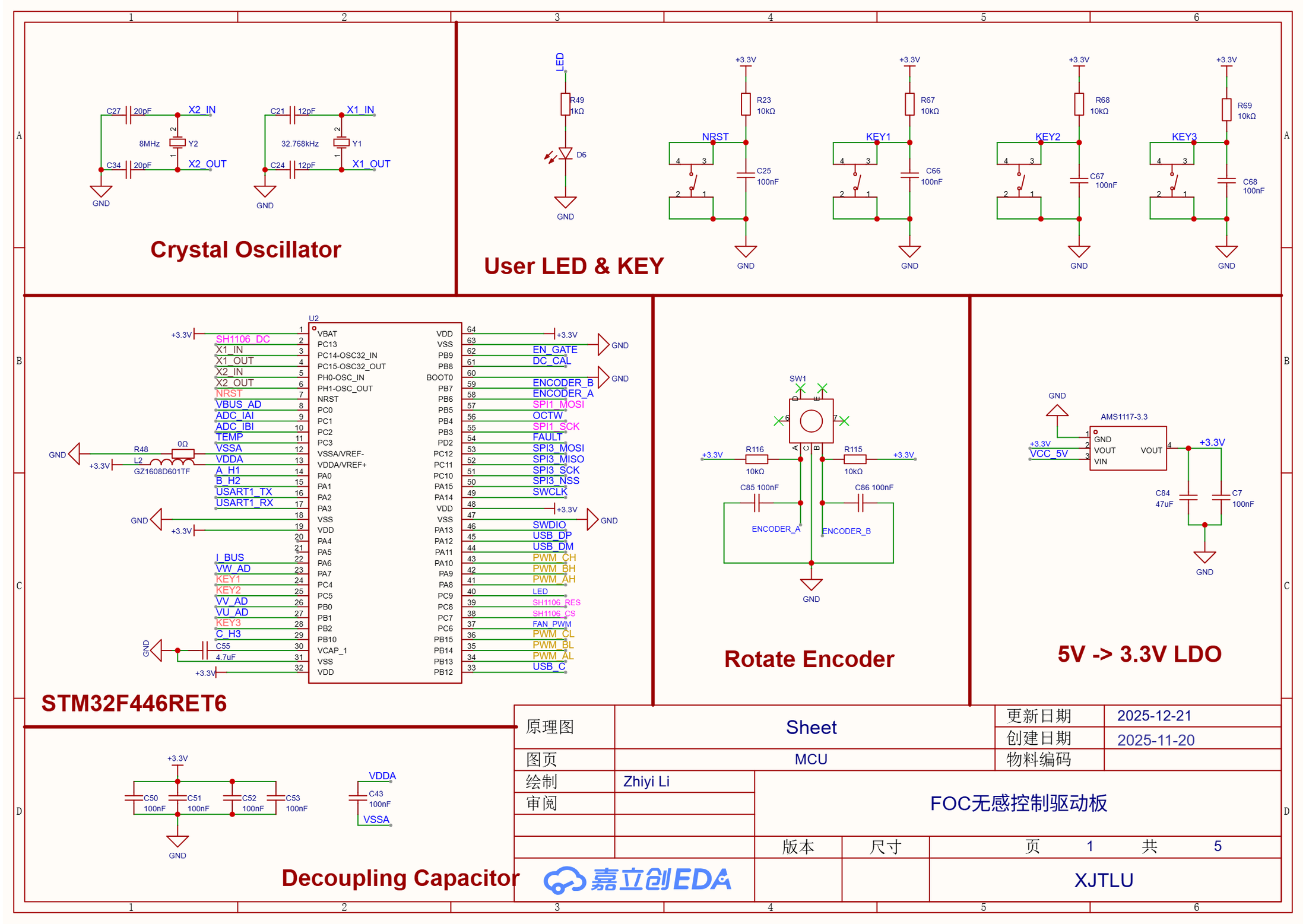
I chose an STM32F446RET6, DRV8301DCAR, and six HY3010D MOSFETs for the controller, gate driver, and three-phase power stage. Five schematic sheets organize control and timing, connectors, analog sensing, the power stage, and gate-drive interfaces. They allow the path to be followed from Ia and Ib sensing through six complementary PWM signals to the U/V/W output. Hall and encoder interfaces were retained for later experiments.
我选了 STM32F446RET6、DRV8301DCAR 和六颗 HY3010D MOSFET,构成主控、栅极驱动与三相功率级。五张原理图分别整理控制时序、连接器、模拟采样、功率级与驱动接口,能顺着 Ia、Ib 采样一路检查到六路互补 PWM 和 U/V/W 输出。Hall 与编码器接口也预留了下来,方便后续实验。
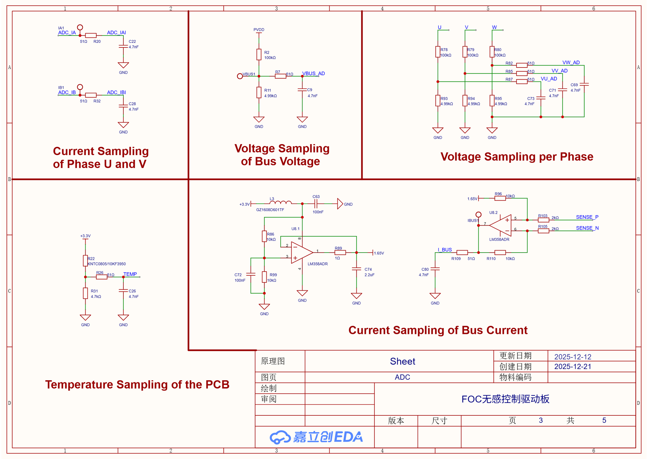
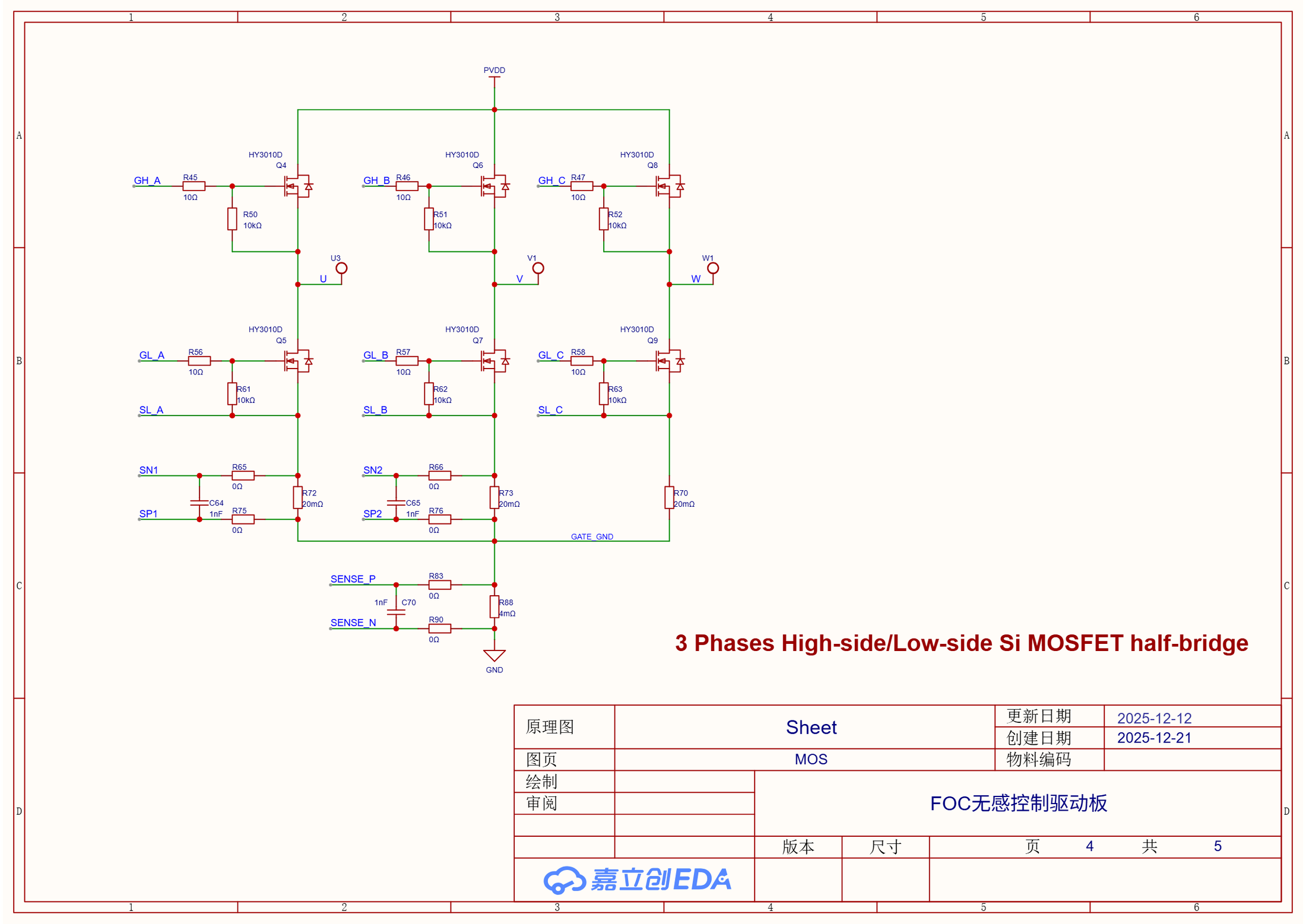
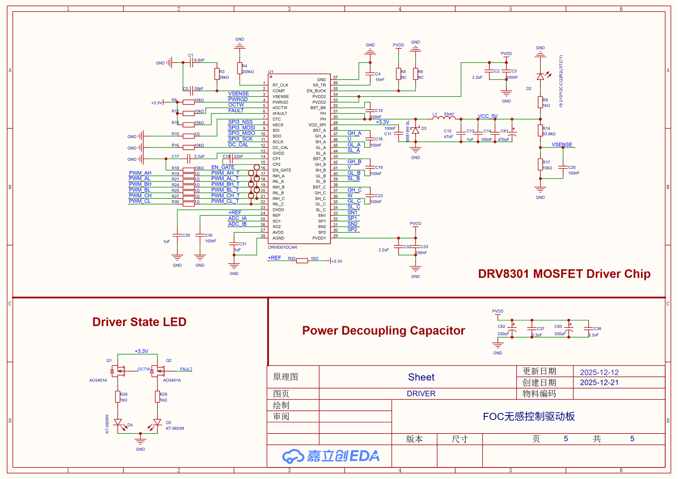
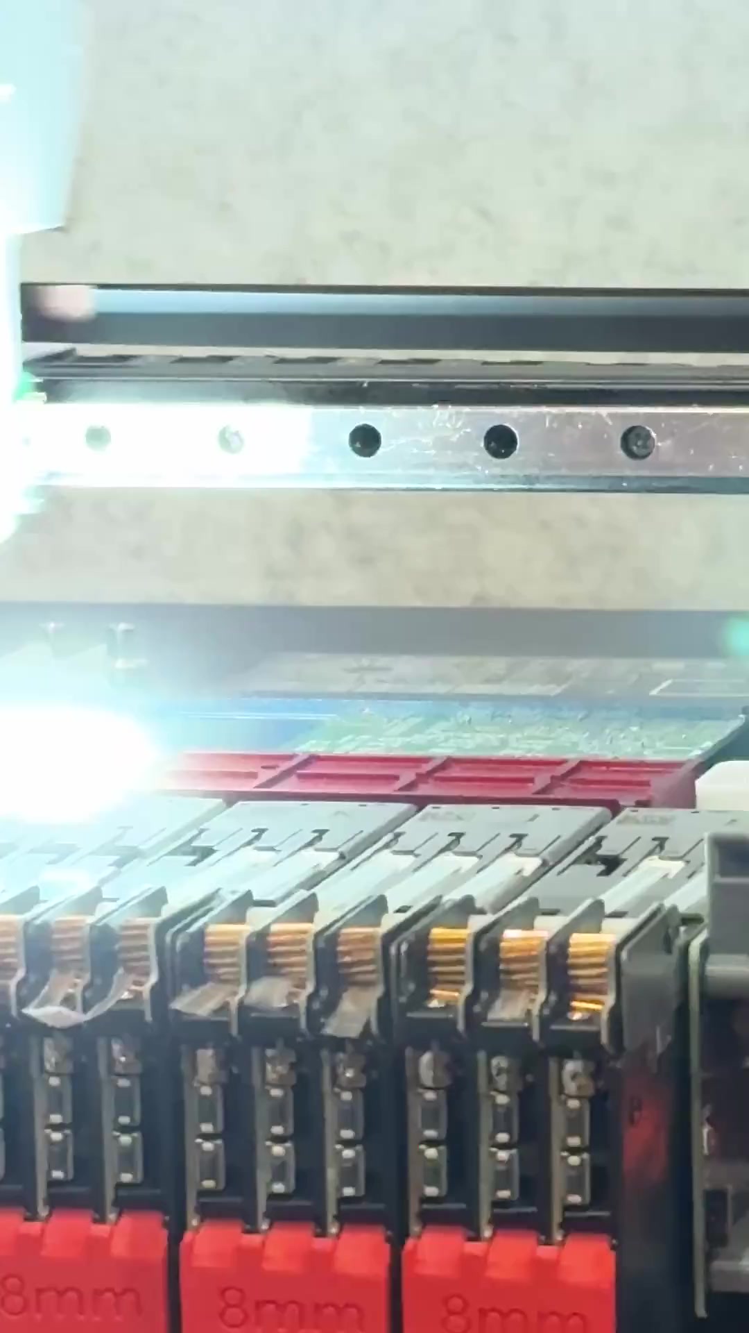
After completing the design, I exported Gerber and BOM files, placed the order, and operated the SMT equipment myself, loading feeders, setting placement coordinates, and running the machine. Rework, hand soldering, assembly, and power-on checks followed. The onsite SMT video records this exact board. Component placement and connections that I had handled on the drawing now had to survive assembly and electrical checks.
设计完成后,我继续做 Gerber、BOM 导出和下单,并亲自操作 SMT 设备,包括上料、设置贴片坐标、运行机器,再补焊、手焊、装配和上电。现场 SMT 录像拍的就是这块板。以前在图纸上处理的是器件位置和连线,现在每一个决定都要经过装配和上电检查。
Board Adaptation板级适配
The work paused over the February holiday and after term resumed in March. I returned to concentrated hardware debugging in April and May. Starting with the Clarke, Park, current PI, inverse Park, SVPWM, and EKF algorithms in an open-source FOC example, I adapted it from an ordinary three-wire brushless motor to my board and this compressor.
项目在 2 月寒假和 3 月开学后暂停过,4 月、5 月才重新集中做实物调试。我从开源 FOC 示例的 Clarke、Park、电流 PI、反 Park、SVPWM 和 EKF 算法开始,把面向普通三线无刷电机的示例适配到自己这块板和这台压缩机。
I led pin, peripheral, and sensing-scale adaptation, connected the OLED, buttons, and EC11, then worked on compressor startup and the protection state machine. Voltage, current, driver faults, and restart conditions all needed physical checks. Matching pins was still some distance from reliable compressor operation. Startup load and fault behavior could not be explained solely by the example's defaults.
我主导板级引脚、外设与采样换算的适配,接入 OLED、按键和 EC11,再处理压缩机启动与保护状态机。电压、电流、驱动器故障和重启条件都需要在实物上检查。引脚能对应上,离压缩机可靠运行还差不少工作,启动负载和故障反应不能只靠示例代码里的默认值解释。
During the observer investigation, I reviewed code with Codex. It helped implement RAM tracing, correct EKF parameters, and identify overwritten Kalman-gain values. I selected experiment conditions, operated the hardware, assessed sound and vibration, checked startup behavior, and decided which changes to keep. I carried those changes into the firmware repository.
后续排查观测器时,我与 Codex 一起读代码,由它协助实现 RAM trace、修正 EKF 参数,并定位 Kalman 增益被覆盖的问题。我负责选择实验条件、操作硬件、判断声音与振动、检查启动状态,再决定保留哪些修改,逐步更新到固件仓库。
Running the Compressor压缩机运行
Stable 45 Hz open-loop operation gave me the first repeatable condition for checking changes. I then retained 30, 45, and 60 Hz test points to compare mechanical response and electrical trends. The final low-speed EC11 version exposed a 30 to 80 Hz electrical-frequency command range on a 12 V bus.
45 Hz 稳定开环运行,是第一个能反复用来检查修改的状态。我随后保留了 30、45、60 Hz 三个测试点,对照机械响应和电气趋势。最终低速 EC11 版本在 12 V 母线下开放了 30 到 80 Hz 的电频率指令范围。
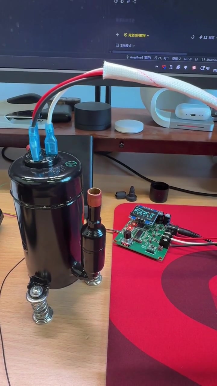
The runtime video shows that final version. Both suction and discharge ports were open. Near the end I restricted the suction inlet by hand and observed continued operation. At the bench, the suction felt strong and the noise sounded low.
运行视频拍的是这个最终版本。当时吸气口、排气口都敞开,后段我用手限制吸气口,驱动仍继续运行。在工作台上,能感觉到明显的吸力,听起来噪声也较低。
Earlier, I had tried the same compressor with a low-cost sensorless board intended for small fan motors. It had a speed knob, and I confirmed ordinary six-step commutation with an oscilloscope. Under similar bench conditions, I remember louder sound, more heat, and weaker suction.
此前我还用同一台压缩机试过一块带调速旋钮的低价无感驱动板,它原本面向小风扇电机,我用示波器确认过普通六步换相波形。在相近台架条件下,我记得它声音更大、发热更多、吸力更弱。
Sensorless Handoff无感接管
Once sustained open-loop operation worked, I continued correcting EKF signs, motor parameters, and code defects until estimated speed approached the imposed frequency. Switching to sensorless control still failed. I reconsidered my approach, shifting my attention from estimated speed to the instantaneous angle produced by the observer.
开环阶段能够持续运行后,我继续修正 EKF 的符号、电机参数与代码问题,估计速度逐渐接近外加频率。但一切换到无感接管,运行仍会失败。这让我重新检查自己的判断,把注意力从估计速度转向观测器输出的瞬时角度。
Reading ST's FOC overview now reinforces the role of rotor angle in control. Next I want to check angle error, state convergence, and reference continuity at the transition separately to find out why handoff fails.
现在看 ST 对 FOC 的说明,转子角度本来就是控制所需的信息。接下来,我想分别检查角度偏差、状态收敛,以及切换瞬间的参考是否连续,找出接管失败的原因。
In May 2026, I kept the repeatable 30 to 80 Hz low-speed demonstration version. I still want to complete sensorless control for brushless and servo motors, then investigate robot joints, force feedback, low-speed startup, and high-frequency injection. The immediate question is how to move the observer from producing a plausible reading to supplying information I can actually use for control.
我在 2026 年 5 月保留了能重复运行的 30 到 80 Hz 低速演示版本。后面仍想继续做通无刷与伺服电机的无感闭环,再研究机器人关节、力反馈、低速启动和高频注入。眼前最明确的问题,仍是怎样让观测器从提供一个看似合理的读数,走到真正可以用于控制。
Development Notes开发笔记
Debugging records and technical notes tied to the decisions and artifacts on this project page.与这个项目页面中的设计决策和工程材料直接关联的调试记录与技术笔记。
Public Project Files公开项目资料
Uploaded evidence served from the public asset folder. Use the file index to preview documents, source code, media, PDFs, and downloadable artifacts without leaving the page.这里列出已经上传到公开目录的项目证据。可以在左侧索引里选择文件,在右侧直接预览文档、源码、媒体、PDF 和可下载附件。
board-render-back.png
PNG / 196.3 KB
Related Media相关媒体
Board photos, schematic sheets, videos, and test captures that show this project at specific stages.展示这个项目具体阶段的板卡照片、原理图分页、视频和测试截图。
Custom FOC Board and Compressor Bench自制 FOC 板与压缩机台架
The cover brings the custom driver board and compressor bench into one frame. It represents the learning route and does not imply a completed sensorless takeover.封面把自制驱动板与压缩机台架放进同一画面。它代表这条学习路线,不表示无感闭环已经完成接管。
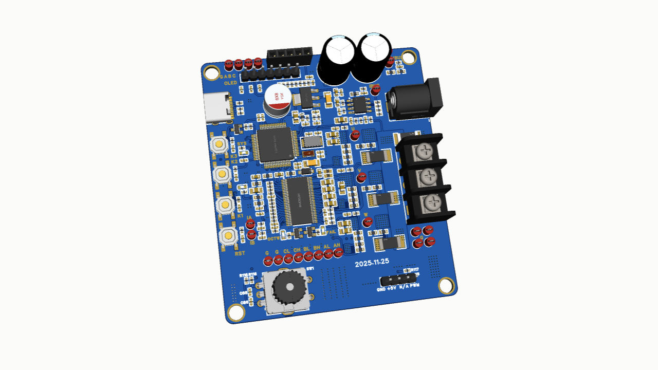
Custom Driver Board Front Render自制驱动板正面渲染
The front render records the STM32F446, DRV8301, six power MOSFETs, controls, and three-phase connector before fabrication. It is layout evidence rather than runtime evidence.正面渲染记录打板前的 STM32F446、DRV8301、六颗功率 MOSFET、交互器件与三相端子。它证明布局内容,不证明运行状态。
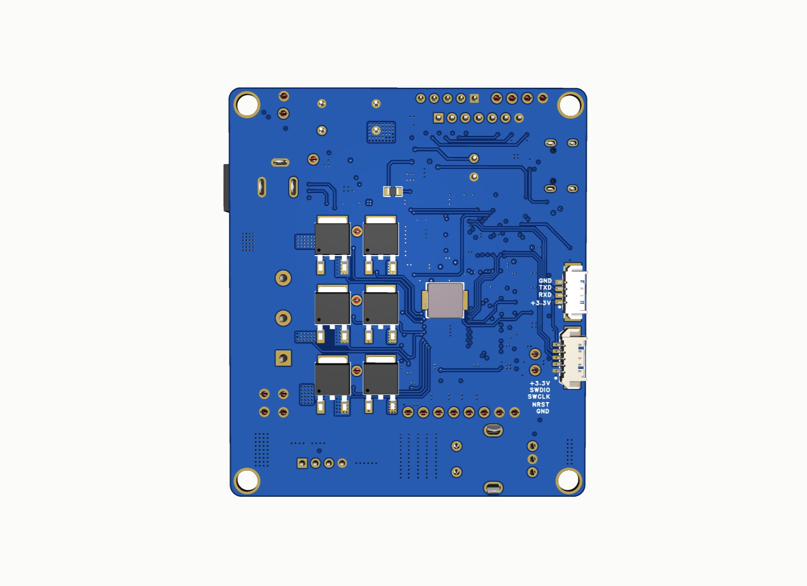
Custom Driver Board Back Render自制驱动板背面渲染
The back render exposes routing and copper distribution on the independently laid out board. It remains design evidence rather than an assembled-board photograph.背面渲染展开我独立 Layout 的走线与铺铜分布。它仍是设计证据,不是装配完成后的实物照片。
STM32F446 Control and Timing SheetSTM32F446 控制与时序分页
This sheet maps six complementary PWM signals, ADC channels, Hall and encoder interfaces, USB, SWD, SPI, and board controls around the STM32F446RET6.这一页围绕 STM32F446RET6 排布六路互补 PWM、ADC、Hall 与编码器接口、USB、SWD、SPI 和板上交互信号。
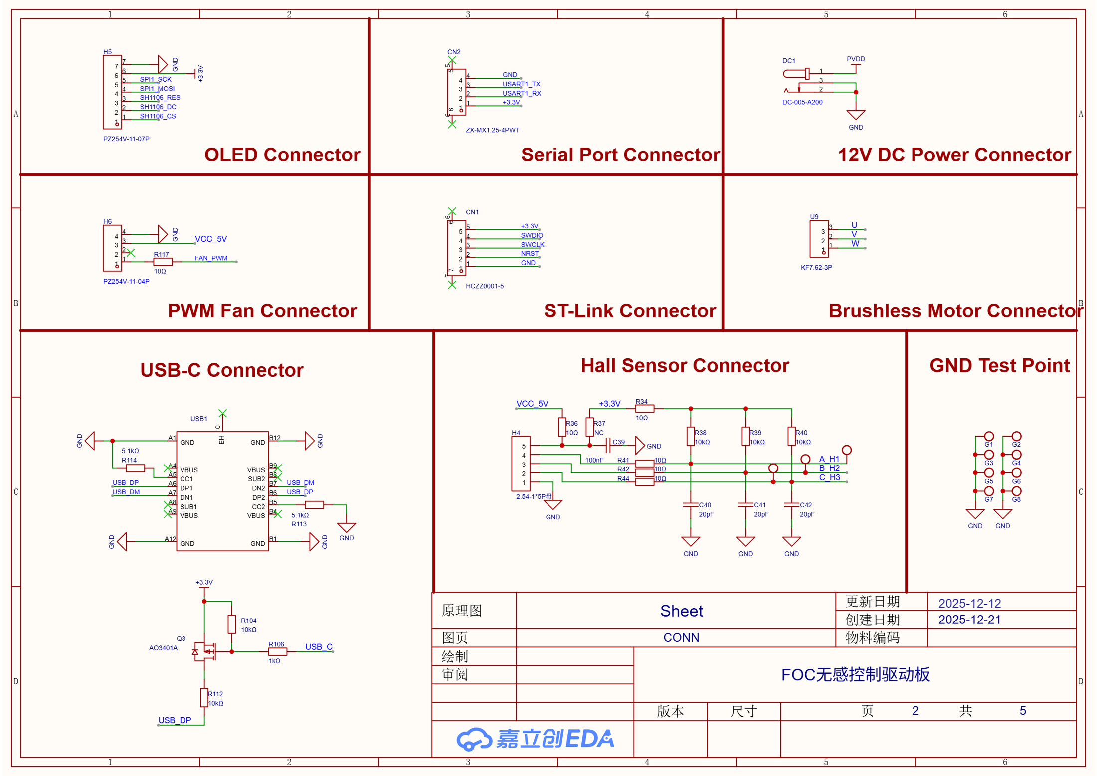
Motor Power and Service Connectors电机电源与调试接口分页
The connector sheet routes U/V/W, Hall inputs, 12 V power, OLED, serial, fan PWM, ST-Link, and USB-C interfaces to the rest of the board.连接器分页把 U/V/W、Hall 输入、12 V 电源、OLED、串口、风扇 PWM、ST-Link 与 USB-C 接到其余电路。
Current Voltage and Temperature Sampling电流电压与温度采样分页
The sampling sheet contains two phase-current channels, bus current and voltage, three phase-voltage dividers, PCB temperature, and the 1.65 V bias path used by the analog front end.采样分页包含两相电流、母线电流与电压、三相电压分压、PCB 温度,以及模拟前端使用的 1.65 V 偏置通路。
HY3010D Three-Phase Power StageHY3010D 三相功率级
Six HY3010D MOSFETs form the U/V/W half-bridges. The same sheet shows 20 mΩ phase shunts and a 4 mΩ bus shunt used by the current-sensing paths.六颗 HY3010D 组成 U/V/W 三组半桥,同页还能看到采样通路使用的 20 mΩ 相电阻与 4 mΩ 母线电阻。
DRV8301 Gate Driver and 5 V SupplyDRV8301 栅极驱动与 5 V 电源分页
The DRV8301DCAR connects six PWM inputs to three gate pairs and exposes SPI, EN_GATE, nFAULT, OCTW, current-shunt outputs, and the 5 V buck stage.DRV8301DCAR 把六路 PWM 接到三组栅极,并引出 SPI、EN_GATE、nFAULT、OCTW、电流采样放大输出和 5 V 降压级。
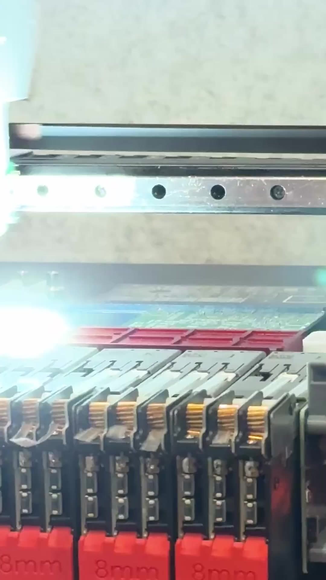
Onsite SMT Feeder and Pick-and-Place Setup现场 SMT 上料与贴片机设置
I loaded the feeders and set the pick-and-place coordinates before operating the SMT equipment for this board. The clip records that manufacturing step.我先完成上料与贴片坐标设置,再操作 SMT 设备生产这块板。视频记录的正是这一段制造过程。
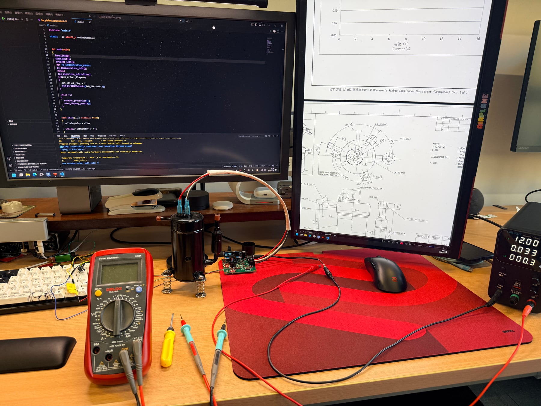
Assembled Board and Compressor Bench装配板与压缩机台架
The 12 V bench photograph shows the assembled board, compressor, supply, measurement tools, and live firmware work. It proves the physical setup rather than refrigeration-loop performance.12 V 台架照片同时拍到装配板、压缩机、电源、测量工具与现场固件工作。它证明实物联调,不证明完整制冷回路性能。
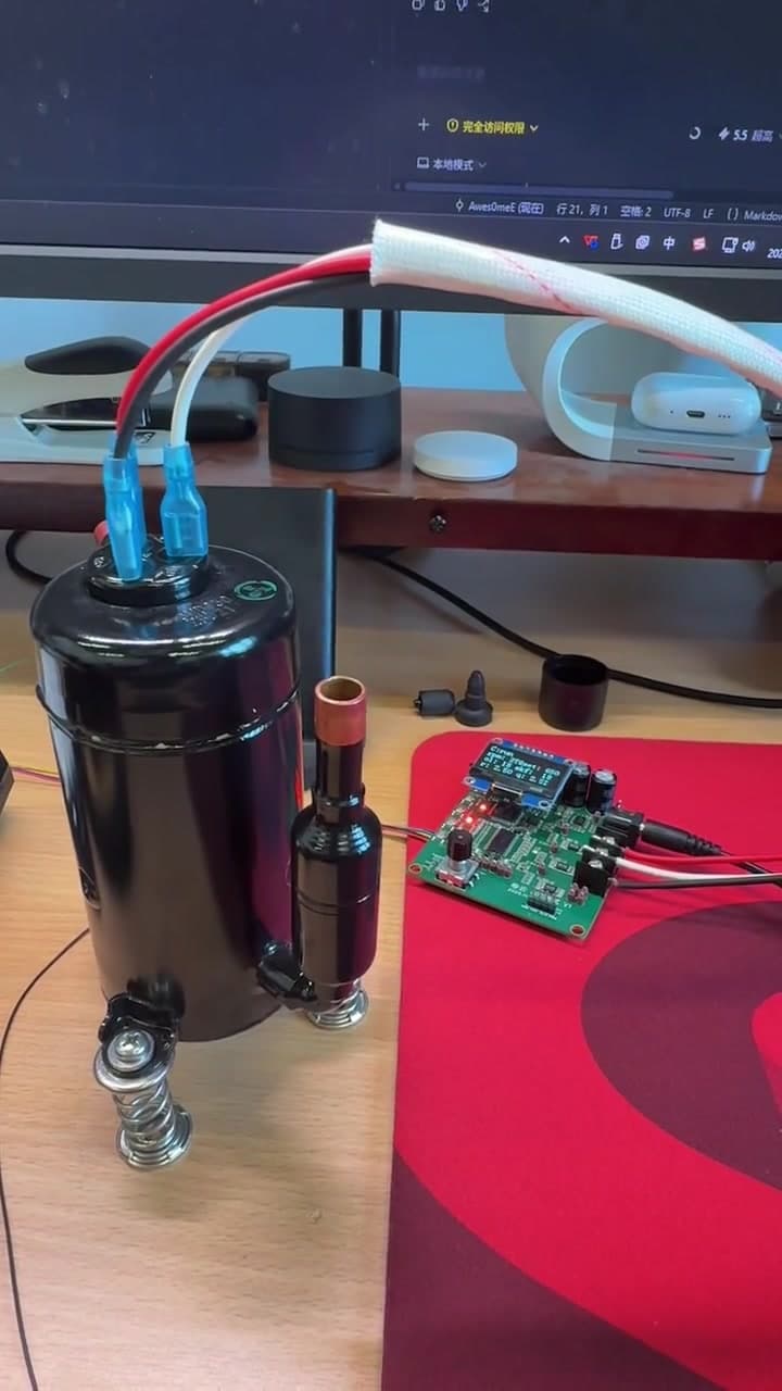
Final Low-Speed EC11 Open-Loop Demo最终低速 EC11 开环演示
The final 30-80 Hz EC11 version records 12 V open-loop operation with both compressor ports open. Manual inlet restriction later in the clip is a disturbance observation rather than pressure or flow validation.最终 30-80 Hz EC11 版本记录 12 V 开环运行,压缩机吸排气口均保持开放。后段人工限制吸气口只是一项扰动观察,不是压力或流量验证。
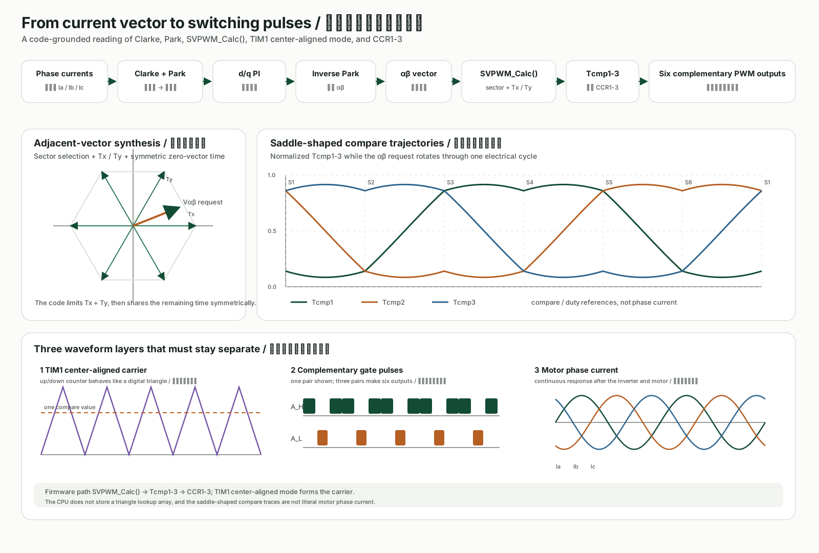
FOC and SVPWM Signal ChainFOC 与 SVPWM 信号链
This original diagram reconstructs the firmware path from Clarke and Park transforms through dq current control to SVPWM compare values, center-aligned PWM, gate pulses, and phase current.这张原创图依照固件重建从 Clarke、Park 与 dq 电流控制到 SVPWM 比较值、中心对齐 PWM、栅极脉冲和相电流的路径。