2025-02-08
PWM, UART, ADC, And Sensor Data PathSTM32 PWM、串口、ADC 与传感器数据通路
A note on PWM output, UART observation, ADC sampling, and why a small calibration table was useful for LED brightness control.记录 PWM 输出、串口观察、ADC 采样,以及用小型校准表把光敏 ADC 值映射到 LED 亮度的过程。
PWM First先看 PWM
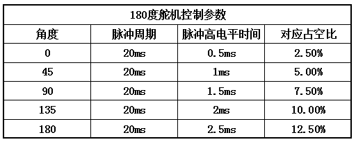
PWM 是第一次把“高低电平”变成“连续效果”的地方。LED 亮度、舵机角度、电机速度都可以从占空比开始理解。只写一句 SetCompare 看起来很简单,但背后要把频率、周期、预分频、占空比和通道关系想清楚。
PWM made the board feel less binary. The same timer idea could drive LED dimming, servo pulses, and motor-speed experiments.
ADC And UART采样和观察
ADC 练习把光敏传感器的模拟量变成数字。串口和 OLED 则负责把这些数字显示出来。这个阶段我才更明显地感觉到:嵌入式调试不能只靠看硬件有没有动,最好能把中间数据也吐出来。
In the metro environment-monitoring demo, brightness control did not only use a fixed ratio. It used a very plain lookup table: LED PWM values were paired with light-sensor ADC values, then linear interpolation estimated the PWM needed for the target brightness. The method was simple, but it pushed the exercise from "the peripheral can output a waveform" toward "data participates in control."
在地铁环境监测小系统里,亮度控制没有只用固定比例,而是做了一个很朴素的查表。表里记录 LED PWM 值和光敏 ADC 值的对应关系,再用线性插值估算目标亮度需要的 PWM。方法不复杂,但它把“外设能出波形”往“数据参与控制”推进了一步。
File文件
The public excerpt keeps the calibration table, PWM limits, and lookup-table interpolation logic: PWM lookup excerpt.
公开摘录保留了校准表、PWM 限幅和查表插值逻辑:PWM lookup excerpt。
Looking Back回头看
Sensor values are usually messy, and a control output does not end at one function call. Even LED dimming needs sampling range, target value, clamping, and real response. Later, when PID came back into view, these small exercises made the formulas feel less detached.
传感器值通常不干净,控制输出也不是一句函数调用就结束。即使只是 LED 调光,也要考虑采样范围、目标值、限幅和实际响应。后面再看 PID 时,这些小练习会让公式没那么悬空。