

Tianjin Jintie STM32 Internship天津津铁 STM32 嵌入式实习
During a month of foundational training at Tianjin Jintie, I planned my own STM32 learning sequence and combined external sensors, display, encoder, servo, and LED control in a working bare-metal demo.在天津津铁一个月的基础实习中,我自行安排 STM32 学习顺序,从外设小实验做起,最后把传感器、显示、编码器、舵机与 LED 控制接进同一套裸机演示。
- Timeline时间线
- 2025.022025.02
- Status状态
- Completed已完成
- Stack技术栈
- STM32Rail TransitEmbeddedKeil MDKInternship

From Arduino to STM32从 Arduino 到 STM32
In February 2025, I spent a month as an embedded intern at Tianjin Jintie Communications, working inside the Tianjin Rail Transit Group headquarters. The supervising engineer supplied introductory material, and my bench held an STM32F103C8T6 Blue Pill, an ST-Link, and external modules. I started with those fundamentals.
2025 年 2 月,我在天津津铁通信有限公司做了一个月嵌入式实习,日常办公地点在天津轨道交通集团总部。工程师给我一批入门资料,桌上是一块 STM32F103C8T6 Blue Pill、一只 ST-Link 和外接模块,我就从这些基础练起。
My university Arduino Nano projects had mostly taught me to call functions and set pins high or low. There was no daily syllabus for this placement, so I combined the supplied material with online tutorials and arranged my own route: GPIO, EXTI and timers, then PWM, UART, ADC, and an integrated demo. I wanted to understand the configuration behind effects that Arduino had made available through a function call.
此前我在学校用过 Arduino Nano,对单片机的理解大多停在调用函数、输出高低电平。工程师没有给逐日课表,我就结合资料和网上教程安排自己的顺序,先 GPIO,再 EXTI 与 Timer,接着学 PWM、UART、ADC,最后把它们接成一个综合 demo。我想弄明白,以前函数调用后直接出现的现象,在 STM32 上到底要经过哪些配置。
First Board Tests第一次上板
Keil's Magic Wand settings occupied me before the peripherals did. Device packs, compiler selection, startup files, library paths, target addresses, and flash algorithms all needed configuration while I was still learning their separate purposes. I eventually split the checks into compilation on the computer, downloading through ST-Link, and an observable effect on the board. Toggling GPIOC13 every 300 ms became the first test across the toolchain and physical hardware.
Keil 的魔术棒设置页先让我卡了一阵。器件包、编译器、启动文件、库路径、目标地址与下载算法都要配置,我却还不清楚它们分别影响哪一步。后来我把检查分开,电脑先能编译,ST-Link 再能下载,最后看板上有没有明确输出。GPIOC13 每隔 300 ms 翻转,成了第一项贯穿工具链与实物的验证。
The initial GPIO and OLED program preserves that setup. It enables GPIOB and GPIOC clocks, establishes OLED power levels through PB4 and PB5, initializes the display, and drives PC13. This was a low-power breadboard exercise; powering a module from GPIO remains constrained by the pin's current capability. I began looking below GPIO_SetBits() at clocks, modes, and registers instead of learning only the function names.
最初的 GPIO 与 OLED 程序还保留着这些配置。先开 GPIOB、GPIOC 时钟,用 PB4、PB5 给 OLED 建立供电电平,再初始化显示并控制 PC13。当时是低功耗面包板练习,用 GPIO 给模块供电也受引脚电流能力约束。我开始主动往 GPIO_SetBits() 下面追,核对时钟、引脚模式和寄存器,而不只记函数名。
At one point the OLED stayed blank even though compilation and download worked. Moving it to another pair of ordinary GPIO pins and using software I²C restored the display.
OLED 曾经编译、下载都正常却不显示。最后我换了一组普通 GPIO,用软件模拟 I²C,屏幕恢复了。
Peripheral Integration外设组合
I ran GPIO, OLED, encoder, servo, DHT11, light sensing, PWM, and UART in separate projects before joining them into one bare-metal program. The hardware remained a Blue Pill, breadboard, and jumper wires. A button selected what the encoder controlled: target light in one mode and servo speed in the other. The OLED showed measured light, target, LED output, temperature, and humidity; UART sent light readings and debug information to the computer, while PC13 served as a status indicator.
GPIO、OLED、编码器、舵机、DHT11、光敏传感器、PWM 与 UART,我先在独立工程里逐个跑通,再加入同一套裸机程序,模块靠面包板与杜邦线连接。按键负责切换编码器的控制对象,一种模式调目标光照,另一种调舵机速度;OLED 显示实测光照、目标、LED 输出和温湿度,UART 向电脑发送光照与调试信息,PC13 留作状态灯。
EXTI handled encoder events, TIM3 paced slower work, and TIM4 generated PWM. Light and temperature/humidity reads waited for a flag; encoder and target updates took place in the main loop. I wrote the application flow, encoder mapping, mode switching, and integrated superloop. The peripheral drivers were material I studied, modified, and connected from ST's Standard Peripheral Library and public examples.
集成时,EXTI 处理编码器事件,TIM3 提供慢任务的触发节奏,TIM4 负责 PWM。温湿度与光敏读取等 flag 到来再执行,旋钮和目标值则在主循环中更新。我编写了应用流程、编码器映射、模式切换与综合主循环,外设驱动是在 ST 标准库和公开例程基础上理解、修改、接入的。
Light Calibration光照标定
To turn a target light value into an LED command, I adjusted PWM point by point and recorded 16 ADC readings on this breadboard, then wrote a lookup and interpolation function. The records span PWM 0 to 1000 and ADC 1600 down to 480. Linear interpolation provides the output for a target between adjacent records.
为了把目标光照数值转换成 LED 输出,我逐点调整 PWM、读取 ADC,在这套面包板上记下 16 组数据,再写了查表插值函数。记录中 PWM 从 0 增到 1000,ADC 从 1600 降到 480;目标位于两个记录点之间,就用线性插值求对应输出。
The program converts the target through the lookup table into PWM, while measured ADC values are displayed and printed. I considered adding feedback correction, but kept this feedforward implementation for the demo.
这套程序根据目标值查表得到 PWM,实测 ADC 用来显示和打印。我当时也想过再加反馈修正,最后先保留了这套前馈实现。
End of the Placement实习结束
I completed this learning sequence independently in about 20 working days. The engineer watched the demo, heard my explanation of how the peripherals worked together, and said I had learned the material solidly. Alongside the practical work, I read introductory material on PID, ATP, ATO, and ATS.
大约 20 个工作日后,我独立完成了这条学习路线。工程师看了 demo,听我解释外设之间怎样配合,评价我学得比较扎实。同期我还阅读了 PID、ATP、ATO、ATS 的入门资料。
Timer, ADC, and PWM returned when I later studied FOC, this time with questions about aligning sampling with switching and finishing calculations in time. The month in Tianjin gave me a starting point for investigating them. Behind a peripheral function, I had learned to look for the clocks, signals, and execution order it depended on.
后来学 FOC 时,我又遇到了 Timer、ADC 和 PWM,只是要求变成了采样与开关时刻的配合,以及一次计算能否及时完成。天津这一个月让我有了继续往下查的起点。遇到一个外设函数,我已经会去找它依赖的时钟、信号和执行顺序。
Development Notes开发笔记
Debugging records and technical notes tied to the decisions and artifacts on this project page.与这个项目页面中的设计决策和工程材料直接关联的调试记录与技术笔记。
Public Project Files公开项目资料
Uploaded evidence served from the public asset folder. Use the file index to preview documents, source code, media, PDFs, and downloadable artifacts without leaving the page.这里列出已经上传到公开目录的项目证据。可以在左侧索引里选择文件,在右侧直接预览文档、源码、媒体、PDF 和可下载附件。
encoder-servo-speed-excerpt.c
C / 506 B
// Condensed from Study_STM32F103C8T6 / encoder knob controlled servo example.
// Evidence scope: mapping encoder count to bounded servo speed.

#include "stm32f10x.h"
#include "servo.h"
#include "encoder.h"

int main(void)
{
    int speed = 0;

    servo_init();
    encoder_init();

    while (1) {
        speed = encoder_count * 50;

        if (speed > 500) {
            speed = 500;
        }

        if (speed < -500) {
            speed = -500;
        }

        servo_set_speed(speed);
    }
}
Related Media相关媒体
Board photos, schematic sheets, videos, and test captures that show this project at specific stages.展示这个项目具体阶段的板卡照片、原理图分页、视频和测试截图。
STM32F103C8T6 Pins and Alternate-Function ReferenceSTM32F103C8T6 引脚与复用功能参考
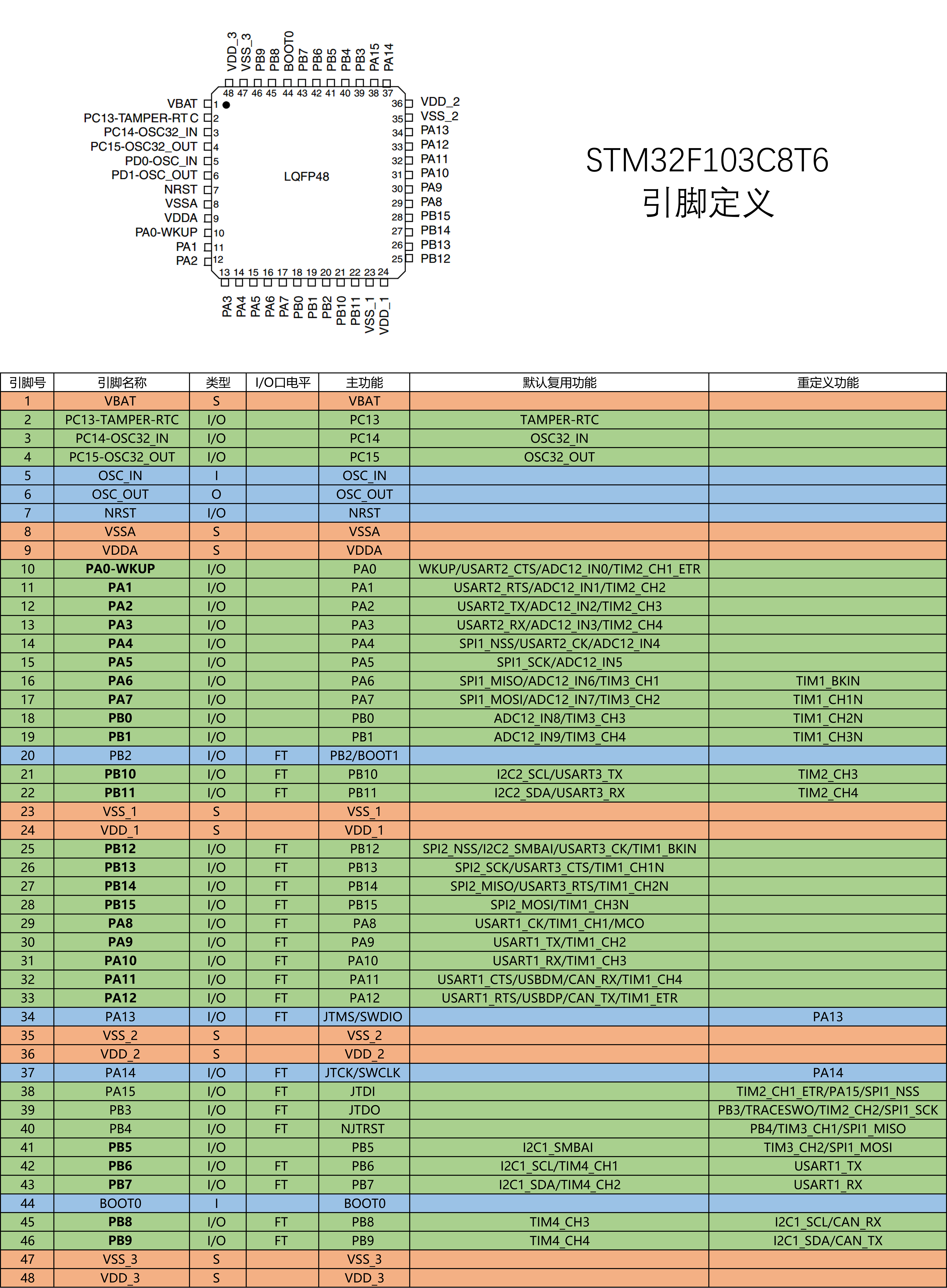
After moving from Arduino pin numbers to STM32 alternate functions, this LQFP48 map became my desk reference. GPIO, USART, ADC, and timers were no longer just function names but real pins whose ports, channels, and alternate mappings had to agree.从 Arduino 的引脚编号转到 STM32 外设复用后,这张 LQFP48 引脚图成了我的桌面地图。GPIO、USART、ADC 与 Timer 不再只是函数名,而是需要同时核对端口、通道和复用关系的真实引脚。

Tianjin Jintie Communications Embedded Internship Cover天津津铁通信嵌入式实习项目封面
This processed Tianjin Rail Transit mark records the setting of the work. I was an Embedded Systems Intern at Tianjin Jintie Communications, based in the Group headquarters, completing self-directed STM32 training and a bench demo rather than production rail-system development.这张处理后的天津轨道交通标志记录项目发生的实习语境。我以天津津铁通信嵌入式实习生身份在集团总部办公,完成的是 STM32 自学与培训 demo,并未参与生产轨道系统开发。
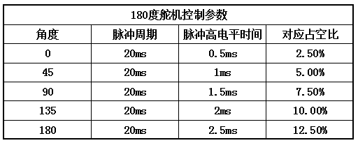
180° Servo Pulse Reference Table180° 舵机脉宽参考表
The servo exercise used this table to map a 0.5–2.5 ms high time within a 20 ms period onto 0°–180°. It is a Timer/PWM setup reference, not an oscilloscope measurement.舵机练习用这张表把 20 ms 周期内的 0.5–2.5 ms 高电平时间对应到 0°–180°。它是配置 Timer/PWM 时使用的参数参考,不是示波器实测波形。