

2026.09.06
Arduino Car Line Sensing and Input AcquisitionArduino 小车的循迹信号与输入采集
Tracing reflected infrared light through the sensor circuit, 74HC165 input thresholds, parallel loading, serial read order, and the code's mapping from bits to sensor positions.从黑线与悬空会触发同一判断的注释出发,沿反射光、电压、电平门限与 74HC165 读取时序,理解每个比特怎样对应车底的传感器。
One comment in the car's infrared test sketch caught my attention while reading it again. Beside if(sensor.ir_left_3), it describes the outermost left sensor detecting a black line or being lifted clear of the surface. Both conditions take the program into the same branch. I want to trace that 1 back through the circuit and find out what happens between light reflecting off the floor and a sensor variable becoming true.
重新读小车的红外测试程序,我留意到 if(sensor.ir_left_3) 后面的一句注释,说的是左侧最外面的传感器“测到黑线或悬空”。黑线和悬空居然会进入同一个判断分支。这个细节让我想顺着代码往前找,看看地面反射的光经过了什么,最后才变成变量里的一个 1。
Reflection and Voltage反射光与电压
The line sensors are ITR20001 devices. An infrared emitter and a phototransistor share the package, facing the target surface, as shown in Everlight's component documentation. The emitter illuminates a small area beneath the car, and the returning infrared light produces current in the receiver. At a suitable mounting height, the difference in reflection between a light floor and black tape can indicate where the line lies.
循迹部分使用 ITR20001。它把红外发光管和光敏三极管放在同一个封装里,朝向被测表面,Everlight 的器件资料给出了这种反射式结构。发光管照亮车底的一小块区域,接收端根据返回的红外光产生电流。在合适的安装高度下,浅色地面和黑胶带的反射差异就可以用来判断线路位置。
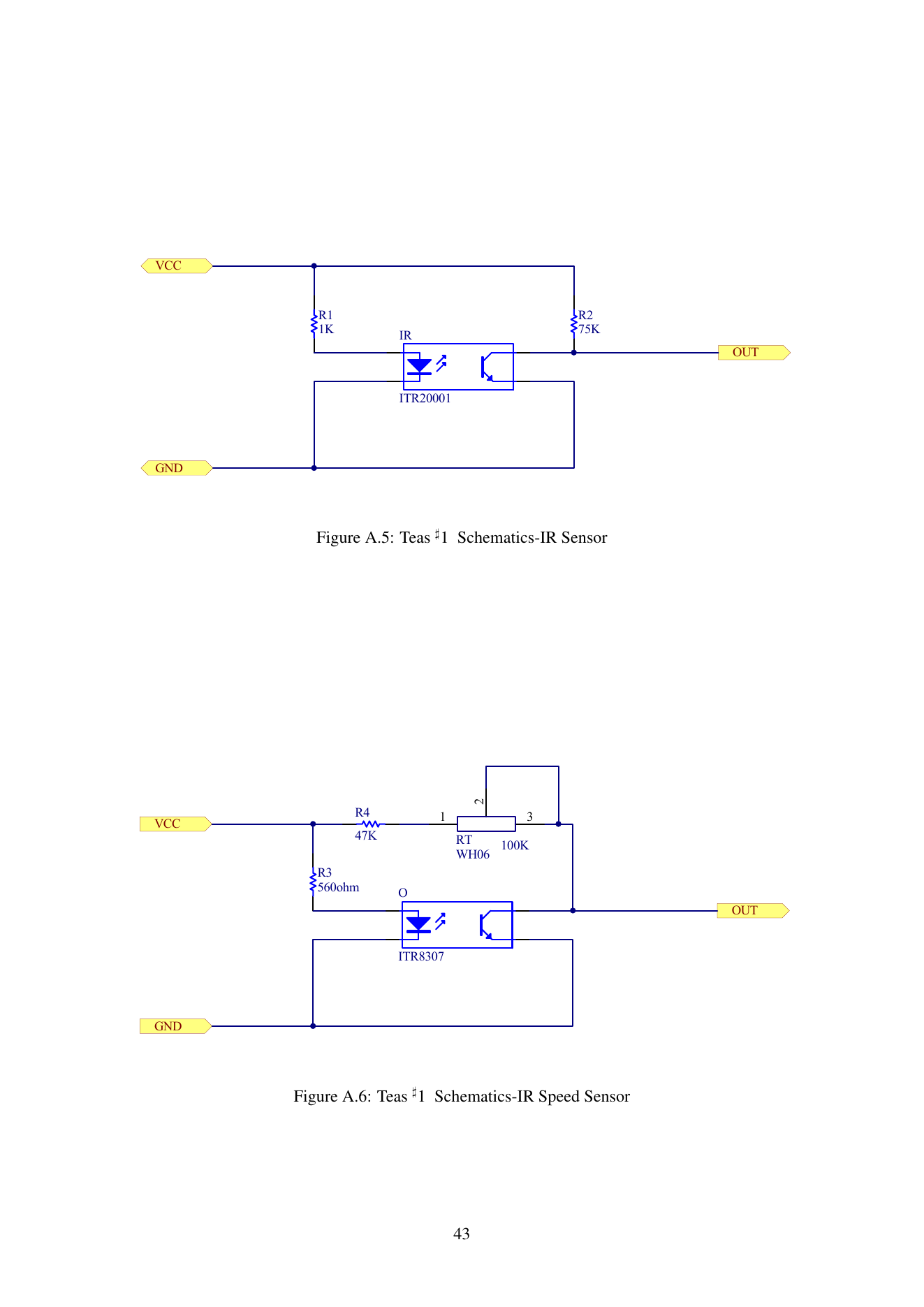
In the upper circuit, R1 limits current through the emitter. The phototransistor has its emitter connected to ground and its collector connected to OUT, with R2 pulling that node up toward the supply. Stronger reflected light increases collector current and lowers the output voltage. As reflection weakens, the pull-up brings the voltage back up. Black tape and an unobstructed view into the distance can both reduce the light returning to the receiver, which explains why the comment groups them together.
图中上半部分是 ITR20001 电路,R1 为发光管限流,光敏三极管的发射极接地,集电极接在 OUT 上,R2 则从电源把这个节点上拉。接收到的反射光较强时,集电极电流增大,OUT 电压降低;反射光较弱时,R2 会把输出拉向电源电压。黑胶带和传感器悬空都可能使返回的光变少,开头那句注释由此就有了电路上的解释。
I would therefore read a high input first as weak reflected light reaching the receiver. Interpreting it as a black line also depends on the sensor's position relative to the track. Raising the chassis, tilting the sensor, or mounting it too far above the floor can change the received light. In Pololu's reflectance-sensor experiment, increasing the distance reduced the voltage difference between the black and white regions. That gives me something specific to watch when following the car manual's test of moving a sensor over black tape: whether my hand changes its height at the same time.
因此,读到高电平时,我首先知道的是接收端得到的反射光偏弱。要把它理解成车底有黑线,还得让传感器与赛道保持合适的相对位置。车身翘起、安装倾斜或离地过高,都可能改变接收到的光。Pololu 的反射式传感器实验也展示了高度变化的影响:在它的对照中,传感器离表面越远,黑白区域的输出电压差越小。看到这个结果,再读小车手册里把传感器移到黑胶带上方的测试方法,我会更注意移动时有没有顺手把高度也变了。
Surface material and ambient light matter as well. Two materials that look equally black to my eyes can reflect infrared differently, while gloss and angle affect how much light returns toward the receiver. Ambient infrared can also reach it. If a change of floor makes the readings erratic, I would hold the position and height steady, compare output voltages, and then observe what changes when external light is screened out. Keeping those changes separate would help identify which condition affects the reading.
地面材质和环境光也会参与其中。肉眼看起来同样黑的两种材料,在红外波段的反射未必一样;表面光泽和角度还会影响有多少光返回接收端。环境中的红外光同样可能被接收。若换一块地面后判断变得不稳定,我会先保持位置和高度不变,比较输出电压,再观察遮挡外来光线后的变化。这样才能逐项看出是哪一个条件改变了读数。
Logic Inputs输入电平
The main schematic takes the line-sensor outputs into one of the two 74HC165 chips. Both the sensors and the registers have supplies labelled 3V3. There is no separate comparator in the phototransistor circuit shown above; OUT can vary over a range of voltages. The 74HC165 input circuit classifies that voltage as a logic level. By the time the program reads a bit, it has the result of that decision, with no way to recover the original voltage from it.
顺着总原理图继续看,循迹传感器的输出接到了两片 74HC165 中的一片,传感器和这两片芯片的供电都标为 3V3。前面的光敏三极管电路没有单独的比较器,OUT 可以在一段电压范围内变化。进入 74HC165 后,输入电路按逻辑电平阈值识别高或低。程序稍后拿到的那个比特,只保留了这个判断结果,原来的电压值已经读不出来了。
It is tempting to put the dividing point at half of 3.3 V. The 74HC165 datasheet instead specifies VIL, the maximum voltage guaranteed to count as low, and VIH, the minimum guaranteed to count as high, under the stated supply conditions. Between them, I cannot assign a dependable 0 or 1 in advance. Reliable detection calls for the two surfaces to produce voltages inside their respective valid logic regions, with margin. Small changes in light or position can flip a reading that sits near a switching threshold.
这里我容易想当然地把 3.3 V 的一半当作分界。74HC165 数据手册列的是保证识别为低电平的电压上限 VIL,以及保证识别为高电平的电压下限 VIH,两者随供电条件变化。中间那段电压不能预先指定成可靠的 0 或 1。要让黑白判断稳定,两个表面的输出就应分别进入可靠的高、低电平区,并留出余量;读数若只在门限附近摆动,光照或位置的小变化就可能让结果翻转。
I can now see the tradeoff in this circuit more clearly. The program gets convenient binary inputs, but the detail in the received light level is lost. Faced with several 1s, I would also consider neighbouring sensors and the chassis position to distinguish a wide dark region from the whole sensor row being too far above the floor. An ir field name makes those physical conditions easy to overlook.
这也让我更清楚地理解了这套电路取舍在哪里。程序只需处理几个开关量,读起来很方便;代价是接收光强的细节没有保留下来。面对一串 1,我还需要结合相邻传感器和车身位置,判断是经过了较宽的黑色区域,还是整个传感器排离地太远。单看一个变量名里的 ir,很容易略过这些条件。
Parallel Load and Serial Read并行装载与串行读取
Seven line sensors, six collision switches, and two buttons occupy fifteen inputs across the two 74HC165 chips. Each register holds eight bits, so cascading them provides a sixteen-bit readout. The course library's pin definitions assign load control to Nano D8, clock to D13, and serial data input to D12. The individual signals connect locally to the registers, then travel back to the controller one after another along the same data wire.
主板把七路循迹输入、六个碰撞开关和两个按键接到两片 74HC165 上,共用十五个输入位置。每片提供八位,两片串接后可以读出十六位。对照课程库的引脚定义,Nano 用 D8 控制装载,用 D13 提供时钟,再从 D12 读取串行数据。多路输入在芯片旁边分别接好,到主控这边就沿同一根数据线依次传回来。
Before reaching the loops in reload_shift_reg(), I stop at LOAD. This macro drives D8 low, waits 1 ms, and raises it again. The 74HC165 loads its parallel inputs asynchronously while `PL` is low. Raising PL ends parallel loading so the contents can be shifted out. Both chips share the load wire, giving all sixteen bits the same loading event. Although transmission is sequential, the input states are retained when that common load ends, subject to the specified setup and hold times around its end.
我读 reload_shift_reg() 时,先停在了循环前面的 LOAD。这个宏把 D8 拉低,等待 1 ms,再拉高。按 74HC165 的工作方式,PL 为低时并行输入会异步装入;恢复为高后结束并行装载,随后可以用时钟移出内容。两片芯片共用这根装载线,所以这一轮读到的十六位来自同一次装载。串行传输有先后,输入状态却是在同一次装载结束时保留下来的;各路输入需要在装载结束前后满足手册规定的建立、保持时间。
Clock pulses then move the loaded contents toward the serial output. The course code uses an order I could easily reverse by accident: read D12 first, then generate a rising clock edge. The first bit is already at the output after loading. Reading it before shifting brings in the full sequence; clocking first would skip that bit and offset the following ones. This is the first eight-iteration loop in `comm.cpp`. A second loop fills reg1 the same way.
接下来的时钟负责把已装入的内容逐位向输出端移动。这里有个很容易写反的顺序,课程代码先读 D12,再产生一次时钟上升沿。装载后,第一位已经出现在串行输出端,先读它,再把下一位移过来。若凭直觉改成先打时钟再读数,第一位就会被跳过去,后面的位也会跟着错位。`comm.cpp`中第一个八次循环如下,第二个循环用同样的方法填入 reg1。
for (i = 0; i < 8; i++)
{
    sensor.reg0 <<= 1;
    if (MISO)
        sensor.reg0 |= 0x01;
    CLK_1;
    CLK_0;
}
Each iteration shifts the accumulated value left and places the current input in its least significant bit. After eight iterations, the first bit read has reached bit 7 of reg0, while the last remains in bit 0. The first group fills reg0; the next fills reg1. Here, MISO expands to digitalRead(12), and digitalWrite() generates the clock. Following those macros reveals how this routine actually collects the sequence one bit at a time.
每轮先把之前读到的内容左移一位,再把当前输入放进最低位。八轮之后,第一次读到的比特到了 reg0 的 bit 7,最后一次读到的比特留在 bit 0。第一组八位填满 reg0,下一组填入 reg1。宏名 MISO 在这里展开为 digitalRead(12),时钟也由 digitalWrite() 产生;沿着宏读下去,就能看见这段代码实际是怎样逐位采集的。
Bits and Sensor Positions比特与传感器位置
Once the sixteen bits are in memory, their positions still need to be matched to the physical sensors. The course library assigns bits 0 through 6 of reg0 to the outer, middle, and inner left sensors, the centre sensor, then the inner, middle, and outer right sensors. The centre field, ir_mid, uses the mask 1 << 3. As a worked example, reg0 = 0b00001000 has only bit 3 high, producing ir_mid = 1 and six other fields set to 0. The first bit received ends up at the top of the byte, while the leftmost sensor is assigned to its lowest bit. I need to check transmission order and physical order separately.
十六位读完以后,还要把存储位置和车上的实际位置对应起来。课程库把 reg0 的 bit 0 到 bit 6,依次分给左侧最外、左侧中间、左侧靠内、正中、右侧靠内、右侧中间和右侧最外的七颗传感器。正中那颗对应 ir_mid,判断时用的是 1 << 3。我可以拿 reg0 = 0b00001000 作一个计算例子,这时只有 bit 3 为高,解码后就是 ir_mid = 1,其余六路为 0。最先传进来的那一位在字节的最高位,车上最左边的传感器却被分配在最低位,传输顺序和空间顺序要分别对照。
There is another small detail in the decoding expressions. Line inputs use a double logical NOT, such as !!(sensor.reg0 & (1 << 3)), to turn a zero or nonzero masked value into 0 or 1 without changing its truth value. Collision switches and buttons use a single !: pressing them pulls the input low, so the inversion makes a press true. A 1 in the resulting structure consequently has different electrical origins. In a line-sensor field, it corresponds to a high input caused by weaker reflection; in a button field, it corresponds to the low input from a press. I would read the circuit and the inversion expression together when examining this kind of interface.
解码表达式里还有一个小细节。循迹输入用了 !!(sensor.reg0 & (1 << 3)) 这样的双重逻辑非,把掩码得到的零或非零数统一成 0 或 1,同时保留原来的真假关系。碰撞开关和按键则只用一次 !,因为按下时输入被拉低,需要反过来表示按下状态。于是,结构体里同样的 1,在循迹字段中对应较弱反射形成的高电平,在按键字段中却对应按下形成的低电平。以后读这一类接口,我会连着输入电路和取反表达式一起看。
The same sensor.ir_left_3 field can be true over black tape or with the sensor lifted clear of the surface. Accurate capture by the 74HC165 cannot distinguish those situations on its own. Interpreting the bit still depends on the sensor's position and the reflected light reaching it. The mounting conditions beneath the car belong in the interpretation of that small if, too.
黑线和悬空都可能让 sensor.ir_left_3 为真。74HC165 把电平读得再准确,也不会替程序分辨这两种情况;判断还要依赖传感器实际放在哪里、收到了多少反射光。代码里的一个 if,因此也要连着车底的安装条件一起理解。