

2026.09.06
Arduino Car Power and Wheel-Speed MeasurementArduino 小车的供电与轮速测量
Following the car’s battery and logic rails through L293D drive and PWM, then deriving wheel rpm from optical marks, interrupt timing, and the course library’s feedback routine.沿电池与逻辑电源追到 L293D 和 PWM,再从轮子标记、中断计时推导 rpm,读懂课程电机库里的反馈调速。
The battery, motors, and controller all connect to the same PCB on this Arduino car. Looking at the circuit again, I want to follow what changes when the battery voltage changes. Tracing power out to the wheels, then following the speed signals back into the program, gives me a more concrete view of how the supply and control work together.
电池接在这辆 Arduino 小车的主板上,电机和主控又从同一块板子取电。我现在重新看这套电路,想先弄清楚一件事:电池电压改变以后,究竟哪些地方会跟着变?顺着电源往车轮查,再沿测速信号回到程序,供电和控制之间的关系就具体多了。
Battery and Logic Supply电池与逻辑电源
In the kit schematic, the positive battery connection splits after the switch. One path goes straight to the L293D motor supply, labelled VC. The other feeds an L7805CV, whose 5V output supplies the Nano board and the driver's logic. Both paths share ground. The controller's logic levels select a drive state, while the battery-to-driver path carries the main motor current.
套件原理图里,电池正极经过开关后分成两路。一路直接接到 L293D 的电机电源脚,图中叫 VC;另一路进入 L7805CV,输出标为 5V,供给 Nano 主控板和 L293D 的逻辑部分。两路共地,电压各有用途。主控发出的高低电平负责选择驱动状态,电机需要的主要电流沿电池与驱动器这一路流动。
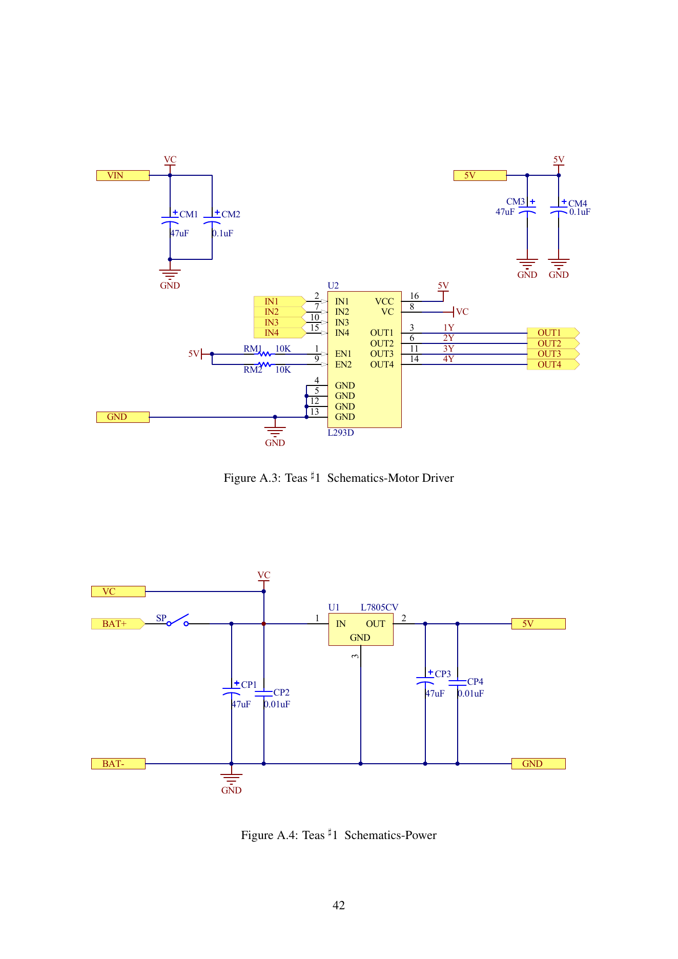
That makes a 9 V battery and a controller operating at 5 V quite compatible along this supply path. Regulation happens before power reaches the controller. To work out what voltage a particular chip receives, I need to find its supply pin and trace the connection back. The battery's nominal voltage and the chip's supply voltage belong at different points in that trace.
这样再看外接 9 V 电池、板上主控工作在 5 V 这件事,就很好理解了。沿原理图的这条供电路径,电压在到达主控之前已经经过稳压。要知道某颗芯片承受多少电压,得找到它的供电脚,再沿着连线往回看。电池标称电压和芯片供电电压,要沿这条路径分别看。
The L7805CV needs some voltage headroom to maintain its 5 V output. ST specifies a typical dropout of 2 V at 1 A output and a junction temperature of 25 °C. A 6 V input therefore calls for more thought than subtracting 5 V and declaring the remaining volt sufficient. Load and battery sag matter too. Starting from 3 V would require a supply arrangement that can boost the voltage. A motor turning after power is connected and every supply in the car meeting its requirements are separate things to check.
不过,L7805CV 要稳住 5 V,输入和输出之间需要留出压差。ST 的 L78 手册给出的典型压差是 2 V,条件为输出 1 A、结温 25 °C。因此,拿 6 V 去供电时,不能只算出它比 5 V 多了 1 V,就认为稳压已经有保证;还要看负载和电池带载后的电压。3 V 输入则需要另一种能升压的供电方案。把电池接上后某只电机能够转动,和整车各路电源都满足要求,是两件需要分别判断的事。
Raising the input voltage introduces a different practical concern. Ignoring the regulator's own quiescent current for a first estimate, its dissipation is P ≈ (Vin − 5 V) × I5V. Suppose the 5 V branch draws 100 mA: a 9 V input gives about 0.4 W of heat, rising to 0.7 W at 12 V. The current in that calculation passes through the regulator; the motor branch needs a separate calculation. I find this distinction useful. A higher battery voltage brings a thermal question on the controller side and changes the drive conditions on the motor side.
电压提高又会带来另一个很实际的问题。线性稳压器上的损耗可以先按 P ≈ (Vin − 5 V) × I5V 估算,暂时忽略它自身的静态电流。用 5 V 支路消耗 100 mA 作例子,9 V 输入时约为 0.4 W,12 V 输入时约为 0.7 W。这部分功率会变成热。这里代入的是经过稳压器的电流,电机支路要另算。我觉得这一步很有用,同样是提高电池电压,主控一侧先要考虑散热,电机一侧则会直接改变驱动条件。
L293D and PWML293D 与 PWM
The L293D contains four half bridges, paired so that each pair connects to the two terminals of one motor. Applying a voltage difference drives current through the winding; exchanging the high and low states reverses the drive direction. H-bridge describes the arrangement. TI identifies the L293D output stage as a Darlington sink and a pseudo-Darlington source. I can follow the same current paths when studying a MOSFET motor bridge, but its conduction losses need to be calculated for that device structure.
L293D 有四个半桥,每两个组成一组,分别接在一只电机的两端。让两端出现一个方向的电压差,电流就沿相应方向流过绕组;把两端的高低电平交换,驱动方向也随之改变。这里的 H 桥说的是连接方式。TI 的 L293D 资料把内部输出级写得很明确,用的是达林顿下拉和准达林顿上拉。以后再看用 MOS 管搭的电机驱动,可以沿同样的电流路径去理解,但器件导通时的损耗要按各自的结构计算。
At low supply voltages, those losses are substantial. The L293D electrical characteristics give typical high-side and low-side drops of about 1.4 V and 1.2 V at 0.6 A. A conducting path through the motor includes both, adding up to roughly 2.6 V. Using those conditions in a 6 V supply example leaves about 3.4 V across the motor during the drive interval. Current and temperature affect the drops. This calculation helps me understand the loss; choosing a motor and driver also requires their respective voltage and current ratings.
这个区别在低电压下很显眼。按 L293D 手册中 0.6 A 条件下的典型值,高侧压降约 1.4 V,低侧约 1.2 V。一条经过电机的导通路径要经过两侧,合起来约 2.6 V。若用 6 V 电源作这个条件下的估算,导通期间留给电机两端的电压约为 3.4 V。电流和温度改变后,压降也会变;算出来的数值是用来理解损耗的,选电机和驱动器时还要对照各自的额定电压与电流。
In motor_set_PWM(128, 128), 128 is a drive command. Arduino's PWM documentation describes the default 8-bit range of 0 to 255, with 128 giving approximately half duty. On this board, resistors pull both enable inputs high, and PWM is applied to the bridge inputs. During one part of the cycle the motor receives a driving voltage; during the other, both terminals are driven to the same potential for braking. Winding current continues to change through the available recirculation paths. A fraction of time spent driving is a better way to read the command than assigning 128 a particular wheel speed.
再看程序,motor_set_PWM(128, 128) 中的 128 表示驱动指令。Arduino 的 PWM 文档说明,默认 8 位输出使用 0 到 255 的数值,128 大约对应一半占空比。在这块板上,两路使能端通过电阻上拉,PWM 加在桥的输入端。驱动阶段给电机施加电压,另一个阶段让两端处于同电位,形成制动状态;绕组中的电流还要通过续流路径逐渐变化。把 PWM 当成一段时间内的驱动比例,比把 128 想成某个转速更合适。
There is an easy detail to miss in the motor library. The two sides use opposite drive polarities. For positive commands, the fixed left input is low and the fixed right input is high, so the right PWM uses 255 - right. At this point I would lay out the voltage at each motor terminal over a PWM cycle before interpreting the drive. Looking at only one pin's duty cycle makes it easy to read the right wheel's command backwards.
电机库的实现还有一个容易看漏的细节。左右两侧采用相反的驱动极性。同样传入正数,左侧固定端置低,右侧固定端置高,右侧 PWM 因此用了 255 - right。读到这一步,我会先把一个 PWM 周期里的两端电平分别列出来,再判断电机得到什么电压。只盯着某一个引脚上的占空比,很容易把右轮的意思读反。
Rotation also generates back EMF in the motor. Microchip's brushed DC motor explanation connects speed with back EMF in a permanent-magnet motor, and winding current with torque. A greater load calls for more current to produce torque; at the same supply voltage, speed can fall. When a motor runs at several different voltages, I therefore want to compare speed, load, and heating at each operating point.
电机本身还会随着转动产生反电动势。对照 Microchip 的有刷直流电机说明,永磁有刷电机的反电动势随转速增大,绕组电流产生转矩。负载增大时,电机需要更多电流来提供转矩;同样的供电下,转速就可能下降。由此再看不同电压下电机都能转动,真正需要比较的是各自的转速、负载和发热。
Battery voltage, bridge losses, PWM, and mechanical load all affect wheel motion. Giving both sides the same command does not automatically compensate for differences between the motors or their mechanical resistance. To find out how fast a wheel actually turns, I need to follow the small sensor beside it.
说到这里,电池电压、桥的压降、PWM 和机械负载都会影响轮子的运动。两边填入相同数值,并不会自动消除电机和机械阻力的差异。要知道轮子实际转得怎样,就得把目光移到轮子旁边那颗传感器上。
Optical Wheel Encoding轮子上的光学编码
The speed circuit uses an ITR8307. Its infrared emitter and phototransistor sit together to detect light reflected from a target, as described in Everlight's component overview. Repeating marks on the kit's wheels vary that reflection, converting rotation into a periodic electrical signal. Each wheel has one sensor channel of its own.
小车的测速电路使用 ITR8307。它把红外发光管和光敏三极管装在一起,接收从目标表面反射回来的光,Everlight 的器件说明介绍了这种结构。套件用轮子上交替出现的标记改变反射光强,让转动变成周期性的电信号。每只轮子旁边各有一路传感器,左右两路分别测各自的轮子。
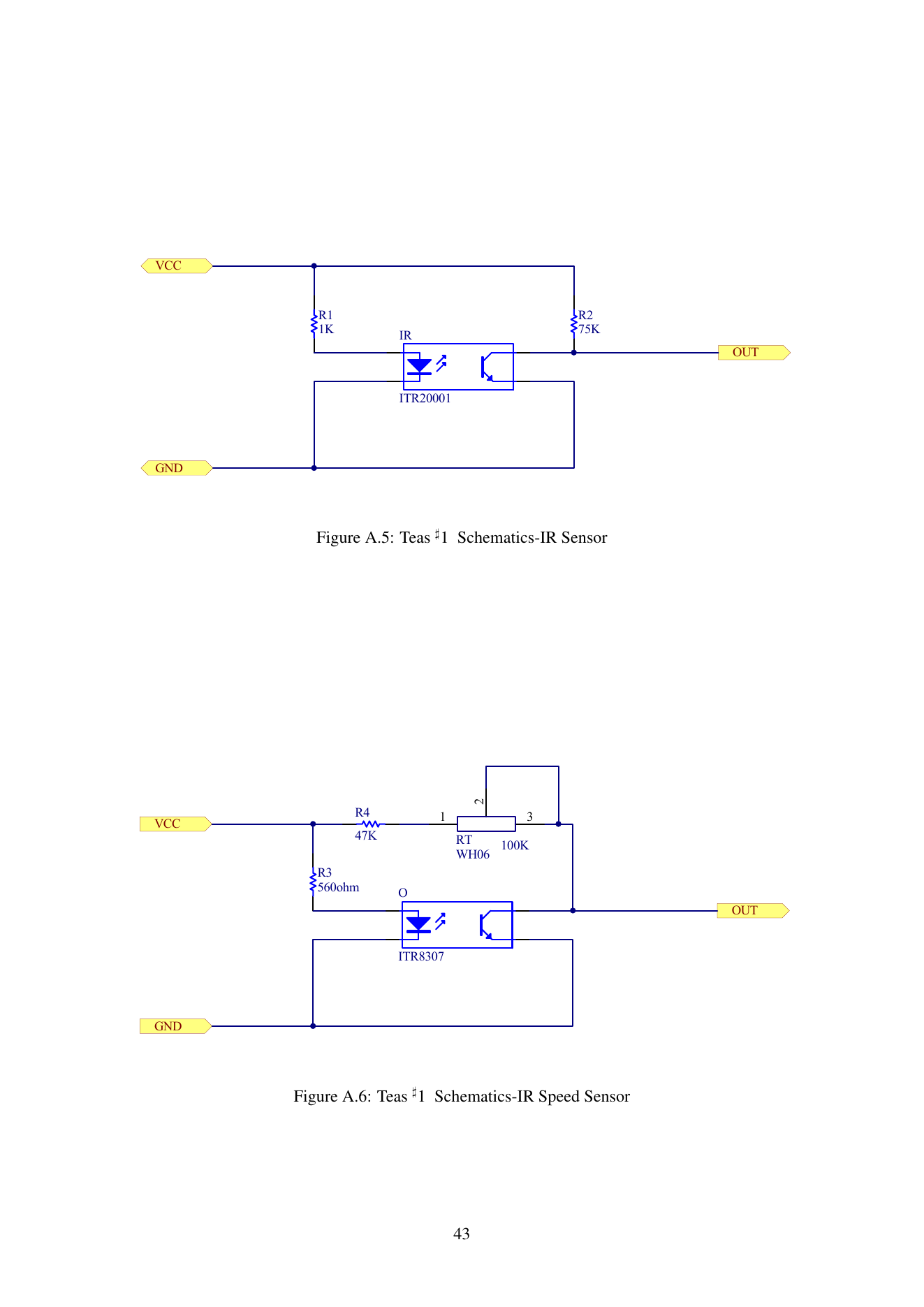
In the lower circuit, R3 limits emitter current, while R4 and the adjustable RT form the receiver's pull-up path. Stronger reflected light increases phototransistor collector current and pulls the output voltage down. As the reflection weakens, the pull-up brings it high again. The main schematic labels the speed-sensor supply 3V3. The controller recognises high and low states at its input thresholds; adjusting the resistance changes how much voltage variation results from a change in light. Sensor distance and surface reflection consequently affect how clearly the pulses can be detected.
顺着图中下半部分读,R3 给发光管限流,R4 和可调电阻 RT 构成接收端的上拉支路。光敏三极管接收到较强反射光时,集电极电流增大,输出电压被拉低;反射减弱时,输出又由上拉支路拉高。总图把测速传感器的供电标成 3V3。主控输入端根据电压阈值识别高低电平,可调电阻会影响光照变化转成电压变化的幅度。传感器和轮子的距离、表面反射条件也因此会影响脉冲是否清楚。
The wheel drawing in the manual has twelve repeating groups around one revolution. Each group contains a light and a dark region, producing one rising and one falling transition as it passes the sensor. The course code selects RISING, so ideally one revolution produces twelve counts. Counting both edges would give twenty-four and require a corresponding change in conversion. One channel per wheel indicates how quickly it turns; identifying direction from the sensor alone would require additional information that distinguishes forward from reverse.
手册的轮子示意图把一圈分成 12 组重复标记。每组有亮、暗两个区段,完整经过传感器一次,输出会经历一次上升和一次下降。课程代码选择 RISING,所以理想情况下每转一圈计到 12 次。若把上升沿和下降沿都计入,计数关系就变成每圈 24 次,后面的换算也得一起改。每轮的一路信号能反映转动有多快;如果还想仅凭传感器判断正反转,就需要增加能区分方向的信息。
Pulses and RPM脉冲与转速
The speed signals connect directly to D2 and D3 on the Nano. The course code registers attachInterrupt(0, left_tri, RISING) and its counterpart using the interrupt numbers for this ATmega328-based board. Arduino's interrupt reference provides the pin mapping and trigger modes. Each rising edge increments a pulse count, and millis() supplies the elapsed time since the preceding rising edge.
测速线直接接到 Nano 的 D2、D3。课程代码中的 attachInterrupt(0, left_tri, RISING) 和另一侧的中断注册,使用的是这块 ATmega328 系列板子的中断编号。Arduino 的中断参考给出了引脚对应关系和触发方式。每出现一个上升沿,程序增加脉冲计数,并用 millis() 记录与上一次上升沿之间的时间差。
The expression 5 * 1000 / float(left_interval) makes me want to account for that 5. Twelve pulses per revolution supplies the missing connection. If consecutive rising edges are Δt_ms apart, the pulse rate is 1000 / Δt_ms per second. Dividing by twelve gives revolutions per second; multiplying by sixty converts it to revolutions per minute.
我看到测速计算里的 5 * 1000 / float(left_interval) 时,先想弄明白这个 5 从哪里来。把每圈 12 个脉冲放进去,单位就能一路算出来。相邻上升沿的间隔若为 Δt_ms,一秒内有 1000 / Δt_ms 个脉冲,除以 12 得到每秒转数,再乘 60 换成每分钟转数。
RPM = (1000 / Δt_ms) × (60 / 12)
    = 5000 / Δt_ms
So the 5 comes from 60 ÷ 12. A 20 ms interval between rising edges gives 250 rpm in this model. It also explains why changing the interrupt mode requires care: count both edges while retaining the old coefficient, and the calculated speed doubles. The number of repeating marks around a physical wheel ends up inside one small constant in the program.
原来 5 就是 60 ÷ 12。例如相邻上升沿相隔 20 ms,按这个模型算出的轮速是 250 rpm。这也解释了为什么不能随手改中断触发方式。若改成双边沿计数,却仍用原来的系数,换算出的速度就会多一倍。硬件上一圈有多少组标记,到了代码里,最后藏在这么一个小常数中。
How does this approach behave when the wheel turns slowly? Counting pulses over a fixed window is another option, but twelve pulses per revolution is fairly coarse. In a 100 ms window, one count represents 50 rpm; extending the window to 500 ms brings that increment down to 10 rpm, at the cost of a longer wait. Measuring the interval avoids having too few counts in a short window, though updates arrive farther apart as the wheel slows. Once it stops, no new edge arrives, so the program needs elapsed time to clear an old speed value. The first edge should also establish the time reference, leaving subsequent edges to produce a speed estimate.
轮子转得很慢时,这种算法会怎样?固定时间内数脉冲是另一种常见做法,但每圈只有 12 个脉冲,若计数窗口取 100 ms,多一个或少一个脉冲,就会相差 50 rpm;窗口延长到 500 ms,每个计数对应 10 rpm,代价是等得更久。测相邻脉冲间隔能绕开短窗口里计数太少的问题,不过转得越慢,两次更新之间也越久。轮子停住后没有新边沿,程序还需要根据等待时间把旧速度清零。第一次边沿也应先建立计时基准,再由后续边沿计算速度。
Wheel-Speed Feedback Control轮速反馈控制
Returning to the course library, I can now read the two motor interfaces more clearly. motor_set_PWM() sets the drive directly. In the branch of motor_step() that requests speed without a travel count, the library compares the target with the calculated wheel speed and adjusts PWM up or down by one count per update. This is where pulse timing enters the control action. It gives a concrete example of feedback adjustment and a reason to check parameter units before choosing values for a function call.
回到课程电机库,两个函数的区别现在更容易读懂了。motor_set_PWM() 直接设置驱动;motor_step() 在指定速度、不指定行进刻度的分支里,会比较目标值与刚算出的轮速,每次把 PWM 向上或向下调整一格。前面那个脉冲间隔的计算,到了这里才真正参与控制。它解释了反馈调速的基本动作,也提醒我先看清函数参数的单位,再决定该给它什么数值。
For further work on this car, I would view target rpm, measured rpm, and applied PWM together for both wheels, alongside battery voltage under load. A slow wheel would then lead to more specific questions: has the drive already reached its limit, or is the speed reading taking too long to update?
如果继续调这辆车,我会把左右轮的目标 rpm、测得的 rpm 和实际 PWM 放在一起看,再记录电池带载时的电压。这样一来,遇到轮子偏慢,就能继续追问,是驱动已经给满了,还是轮速读数更新得太慢。