
Arduino Smart Car Line-Tracking KitArduino 循迹小车焊接与控制实训
I assembled and tested an Arduino car kit, learned to trace its power, sensing, and motor circuits, and helped tune the team’s car to a top-5-percent finish in the campus lap-speed challenge.我从裸 PCB 开始装配 Arduino 小车,逐项检查电源、传感和电机功能,再参与赛道调试;小组最终进入校内圈速挑战前 5%。
- Timeline时间线
- 2024.03 - 2024.042024.03 - 2024.04
- Status状态
- Completed已完成
- Stack技术栈
- ArduinoEmbeddedLine TrackingSolderingMotor ControlCourse Project
Assembly装板
My first embedded project arrived as a bare purple PCB and several bags of components. I was still learning what regulators and capacitors did when it was already time to solder resistors, IC sockets, sensors, switches, and motor connectors. My expectation was simple: install everything correctly and the car should work. Assembly made me unpack that word. Polarity, orientation, joint quality, and the order of installation all mattered beyond getting the leads into the holes.
第一次做嵌入式项目,我拿到的是一块紫色裸 PCB 和几袋元件。那时还没弄明白稳压器和电容各管什么,就已经要把电阻、IC 座、传感器、开关和电机接口焊上去了。我对任务的理解也很直接,把元件装对,小车应该就能跑。真正动手后,才发现这个“装对”包含极性、朝向、焊点和安装顺序,远比把引脚塞进孔里复杂。
The car was an Arduino line-tracking kit for MEC104. I began with assembly, circuit reading, and basic tests, then helped tune it to complete a lap along a black line. The PCB, manual, and test programs came with the kit; my task was to understand their design and make the hardware I had soldered behave accordingly. Working through that gap was what drew me toward the components I had initially known only by appearance.
这辆车是 MEC104 的 Arduino 循迹套件。我从装配、读电路和基础测试开始,参与把它调到能沿黑线跑完整圈的状态。套件已经给出了 PCB、manual 和测试程序,我要做的是理解这些设计,并让自己焊出来的实物按预期工作。也正是在这个过程中,我开始对板上那些原先只认识外形的器件产生兴趣。
Circuit Checks电路与测试
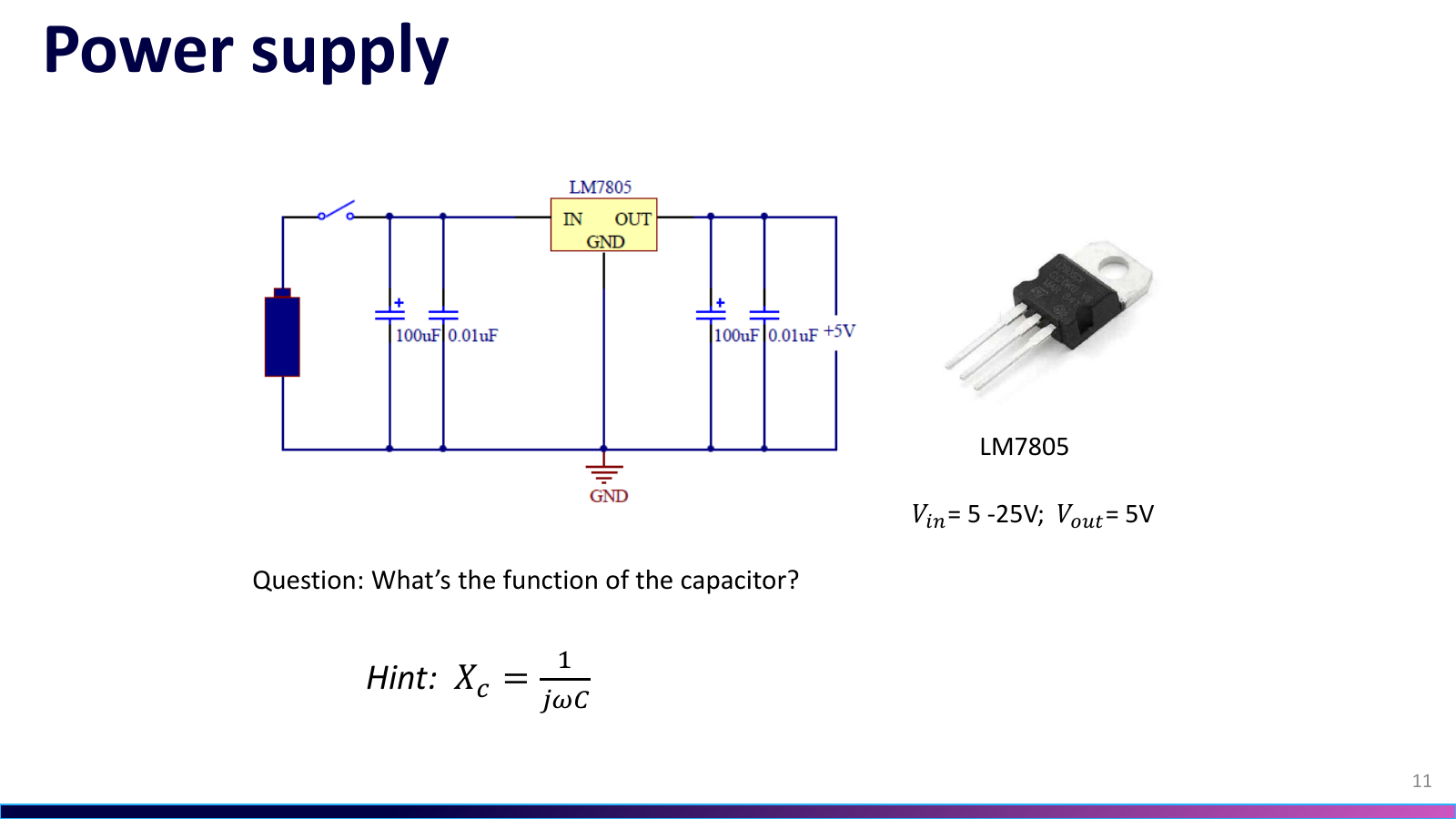
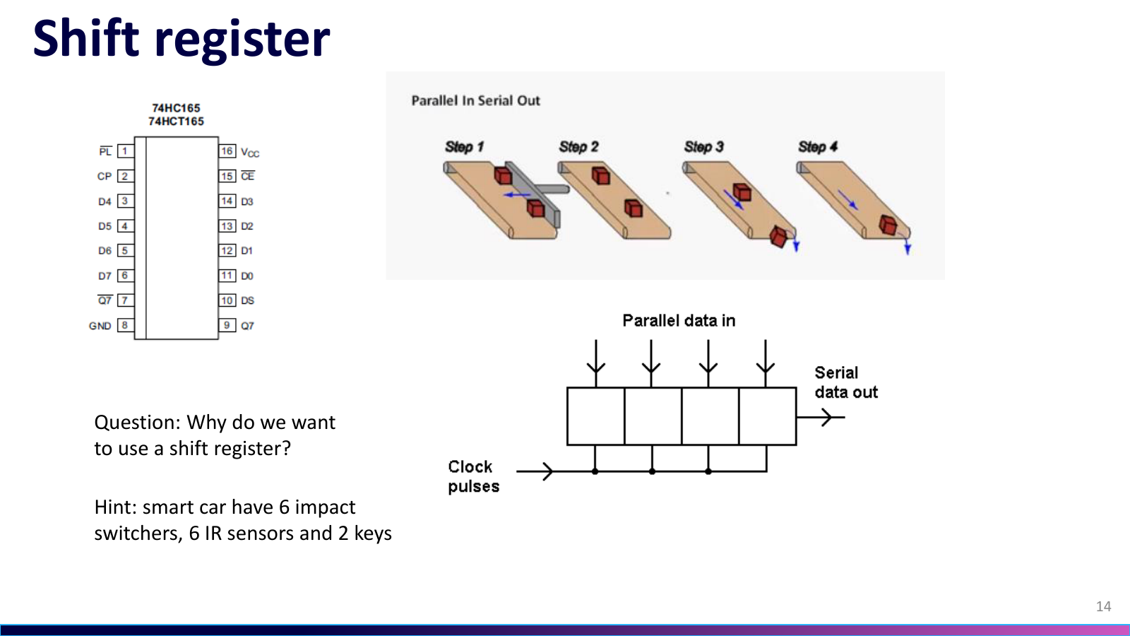
With the board assembled, I used the kit manual to follow its signals. The LM7805 supply section provides the 5 V rail, with capacitors supporting filtering. Two 74HC165 devices bring six collision switches, seven IR tracking inputs, and two keys back to the Nano-compatible controller. Calling reload_shift_reg() refreshes those states before the program chooses an action. Reflected light and physical contact begin as very different interactions; the software receives both as digital states.
焊接完成后,我拿着 套件 manual 顺着信号读板子。LM7805 所在的电源部分建立 5 V 供电,周围电容配合滤波;6 个碰撞开关、7 路红外循迹输入和 2 个按键,经两颗 74HC165 送回 Nano 兼容主控。程序先用 reload_shift_reg() 刷新状态,再决定下一步动作。红外传感器读的是地面反射差异,碰撞开关读的是真实接触,到了程序里才都变成数字状态。
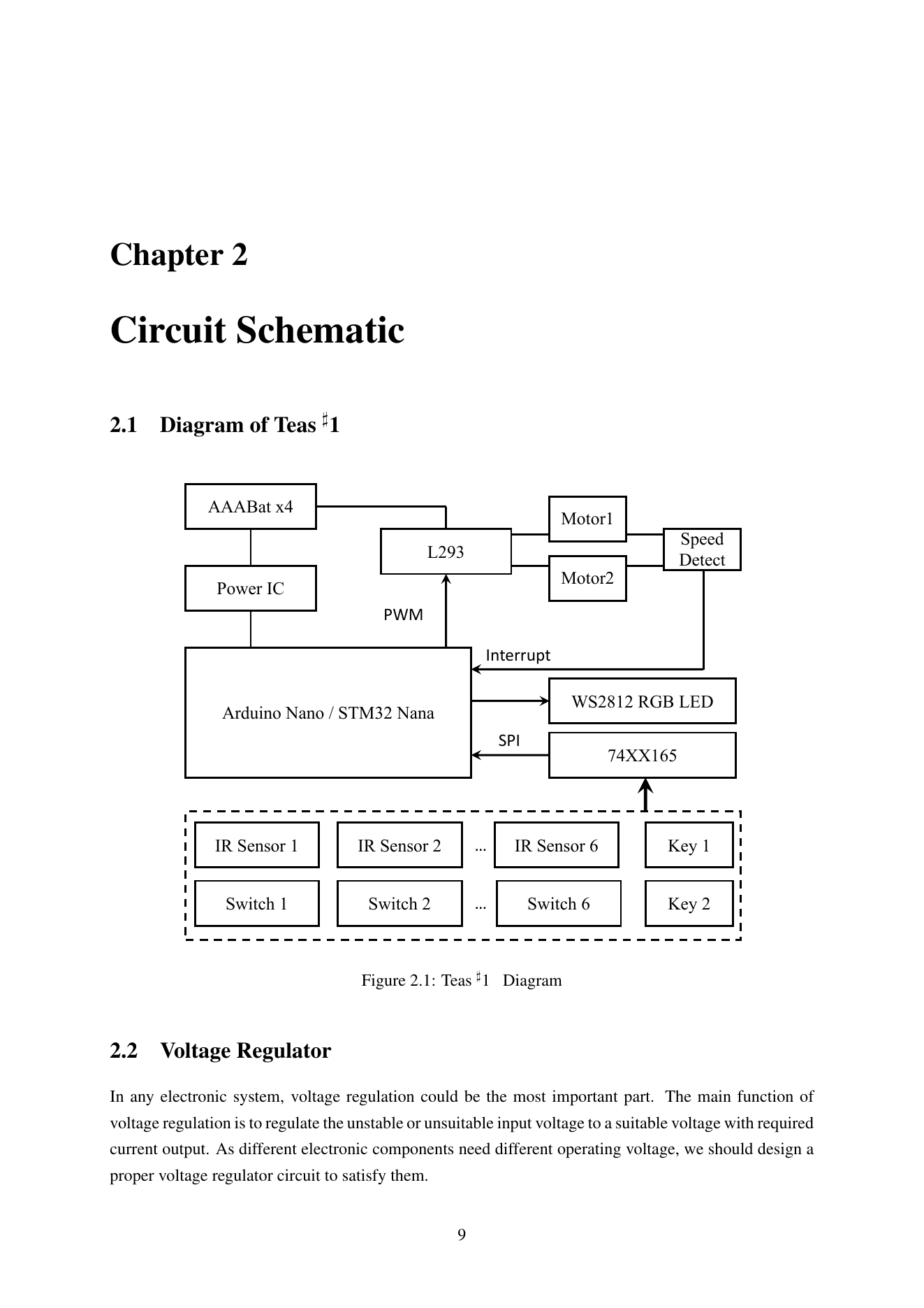
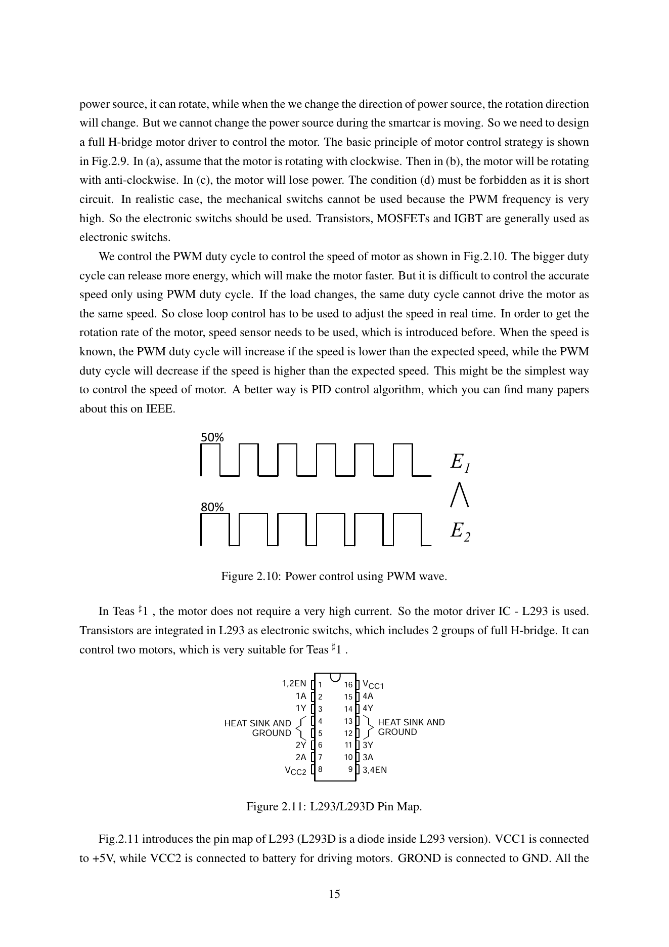
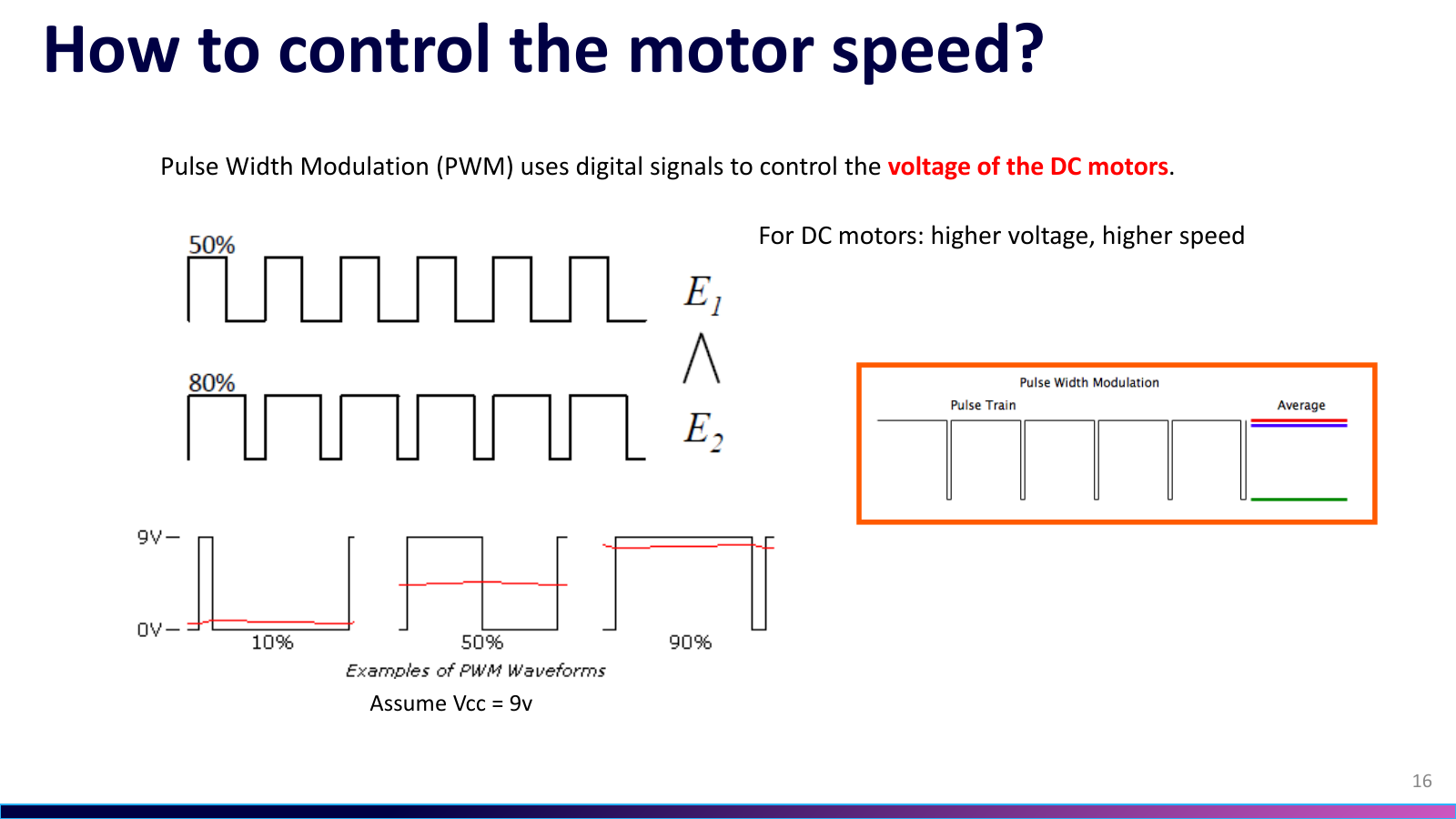
The L293 drives the two DC motors. In motor_set_PWM(left, right), the sign selects direction and the magnitude gives a PWM command up to 255. Watching the wheels made the interface concrete for me: matching commands for forward travel, a smaller command on one side for a turn, and opposing directions for a stronger correction. Reading the L293 datasheet now clarifies the separation between controller logic and the stage supplying motor current. During the project, I built that understanding by observing the car.
输出侧由 L293 驱动两只直流电机。motor_set_PWM(left, right) 的正负号选择方向,绝对值给出最大到 255 的 PWM 指令。我开始能把函数和车轮对应起来,左右相同是直行,一侧减小指令会转弯,两侧反向则能作更强的修正。现在对照 L293 手册,更能看清主控负责逻辑、电机电流由驱动级承担的分工;当时我是看着车轮动作,才逐渐理解这层关系的。
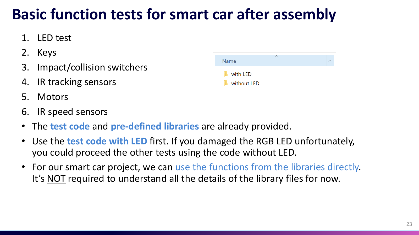
An explanation of the circuit still needed testing. The course split checks into LEDs, keys, collision switches, IR tracking, motors, and speed sensing; the test-code archive retains both with-led and without-led versions. I worked through those small programs before loading the full tracking logic, checking that inputs changed and the expected wheel moved. Once the car was on the track, a steering problem no longer required suspecting every solder joint and the entire program at once.
不过,能解释电路还不够,板子得逐项测。课程把 LED、按键、碰撞开关、红外循迹、电机和测速分成六组测试,测试代码里还留着 with-led 与 without-led 两套版本。我沿着这些小程序检查功能,先确认输入会变、预期的轮子会动,再加载完整循迹逻辑。这样一来,跑偏时至少不用同时怀疑所有焊点和整份程序。
Track Tuning赛道调试
Track work brought straight-line speed and cornering response into the same decision. The project report describes large, medium, and small steering corrections. An outer IR channel calls for a strong response, including opposing wheel directions when needed; an inner channel calls for a smaller speed difference, with a middle grade between them. I helped adjust speed and wheel commands repeatedly so the car could run quickly on straights and recover in corners.
真正上赛道后,要同时顾及直道速度和入弯修正。项目报告记录了大、中、小三档转向。外侧红外通道触发时,偏离已经较大,需要更强的动作,必要时让左右轮反向;内侧通道触发时,只给较小的轮速差,中间再加一档过渡。我参与反复调整速度与左右轮指令,目标就是直道尽量快,到了弯道又能把车收回来。
The report records replacing four dry cells with a lighter 12 V lithium-battery setup.
报告也记录了将原来的 4 节干电池换成更轻的 12 V 锂电方案。
Our car eventually placed in the top 5 percent of the campus lap-speed challenge, which was a satisfying result. What stayed with me was the route from loose parts to a working car. I had to understand assembly, power, sensor reads, and wheel motion individually, then tune them together. It was the first project that made me want to keep going in embedded engineering.
最后,我们的小车跑进了校内圈速挑战前 5%。这个名次当然让人开心。我更清楚地记住了从散件到整车的过程,原来让小车沿黑线跑,需要我把焊接、电源、传感器读取和两轮动作逐个弄明白,再把它们放到一起调。那是我第一次觉得,自己愿意继续往嵌入式这个方向钻下去。
Development Notes开发笔记
Debugging records and technical notes tied to the decisions and artifacts on this project page.与这个项目页面中的设计决策和工程材料直接关联的调试记录与技术笔记。
Public Project Files公开项目资料
Uploaded evidence served from the public asset folder. Use the file index to preview documents, source code, media, PDFs, and downloadable artifacts without leaving the page.这里列出已经上传到公开目录的项目证据。可以在左侧索引里选择文件,在右侧直接预览文档、源码、媒体、PDF 和可下载附件。
car-back.jpg
JPEG / 426.5 KB
Related Media相关媒体
Board photos, schematic sheets, videos, and test captures that show this project at specific stages.展示这个项目具体阶段的板卡照片、原理图分页、视频和测试截图。
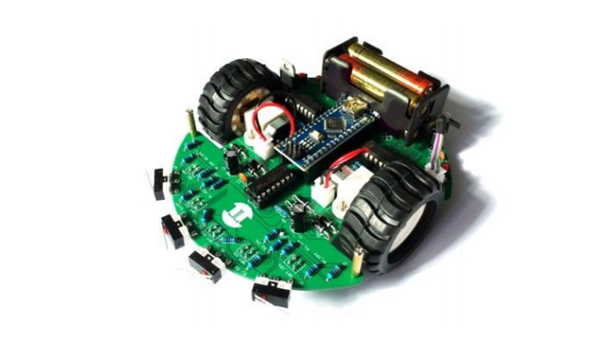
Course Reference Smart-Car Assembly课程参考车装配示意
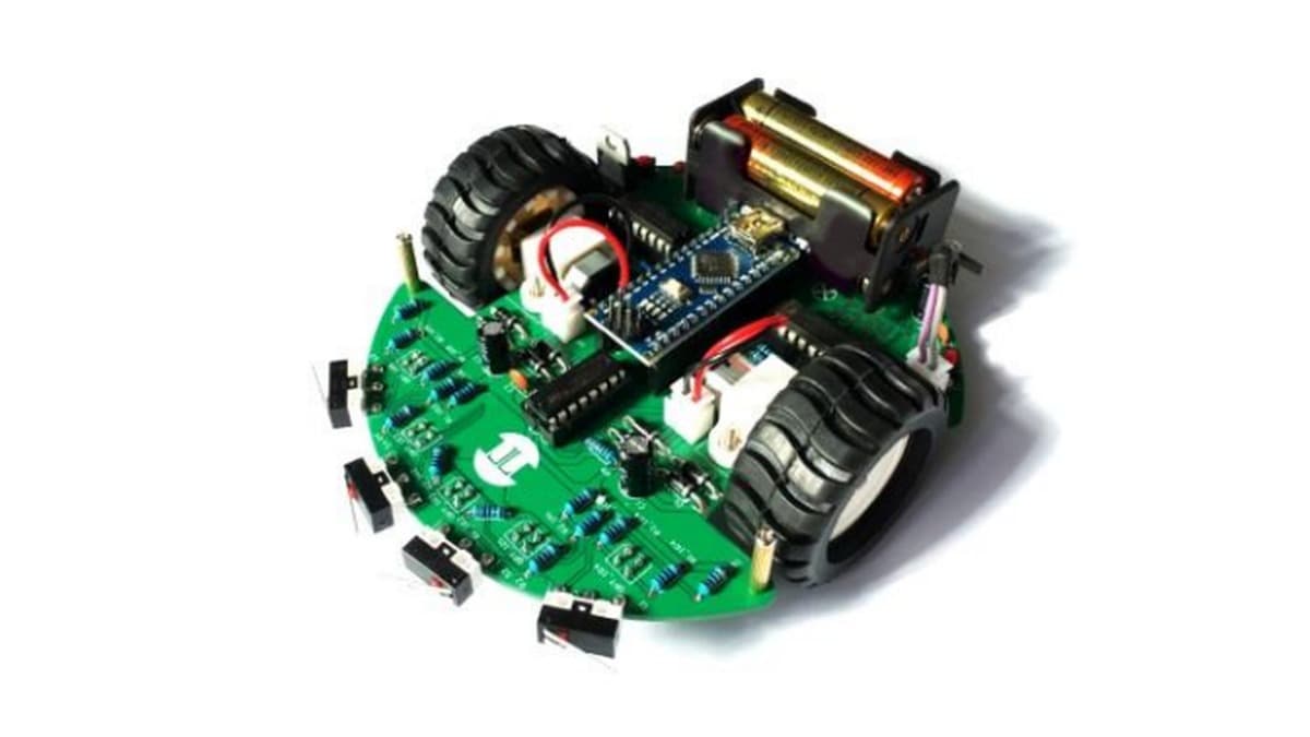
The green reference car shows the kit's intended layout with a Nano-format controller, two driven wheels, a battery holder, and front collision arms. It is not the purple build documented in this project.绿色参考车展示套件的预期布局,包括 Nano 尺寸控制板、两只驱动轮、电池盒和前缘碰撞拨杆;它并非本项目记录的紫色实物。
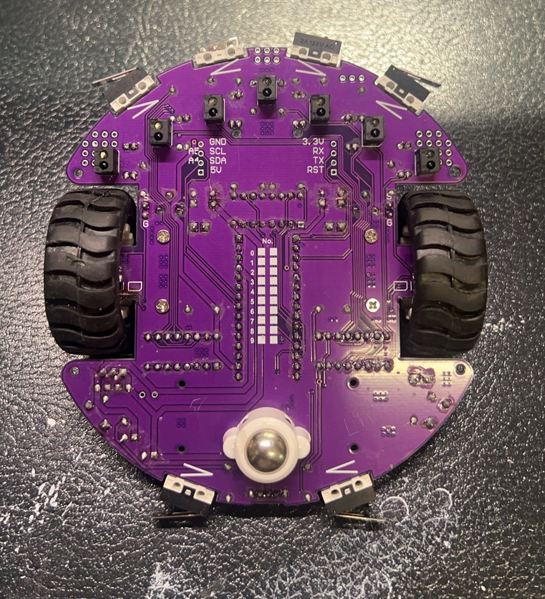
Purple Chassis From Below紫色小车底面
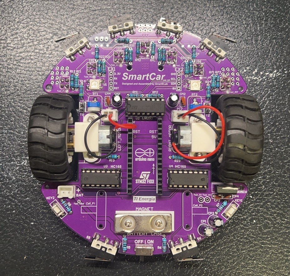
The underside of the assembled purple chassis exposes the through-hole joints, six downward-facing IR tracking sensors, two drive wheels, ball caster, and long-arm collision switches around the edge.装配后的紫色底盘翻到背面,通孔焊点、六个朝下的红外循迹传感器、两只驱动轮、滚珠万向轮和沿板边布置的长臂碰撞开关都直接可见。
Populating the Purple PCB at the Bench在焊台上装配紫色 PCB
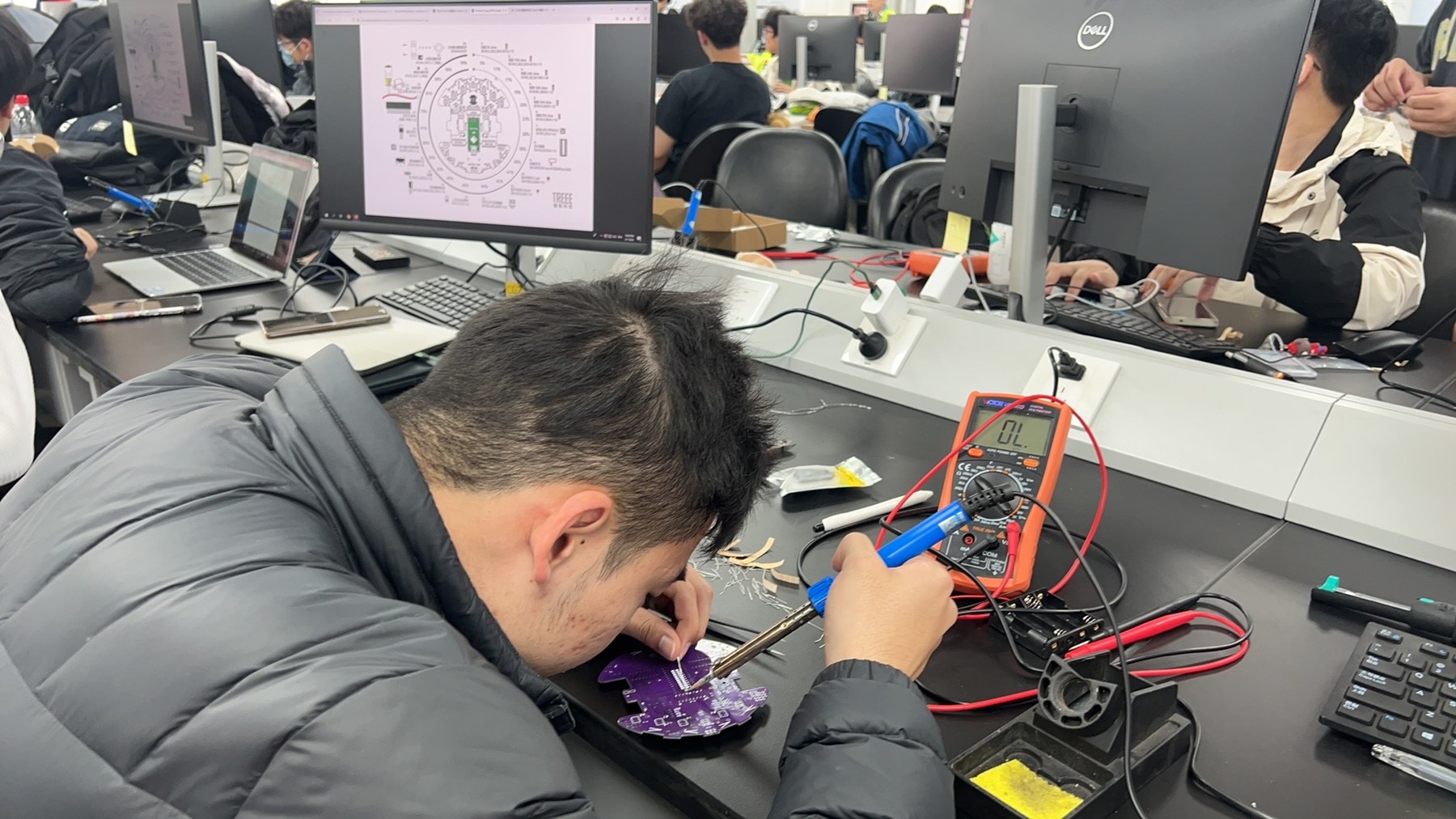
The assembly record catches the board mid-solder, with its circular parts map open on the monitor and a multimeter beside the iron.装配记录停在焊接进行时。显示器上打开圆形元件布局图,电烙铁旁放着万用表。
Power, Inputs, and Motion in One Diagram一张图串起电源、输入与运动
The manual connects four AAA cells through a power IC to the controller, routes PWM through L293 to two motors, and returns six IR inputs, six switches, and two keys through 74XX165.手册把四节 AAA 电池经电源芯片接到控制器,再让 PWM 经 L293 驱动双电机;六路红外、六个开关和两个按键则通过 74XX165 返回主控。
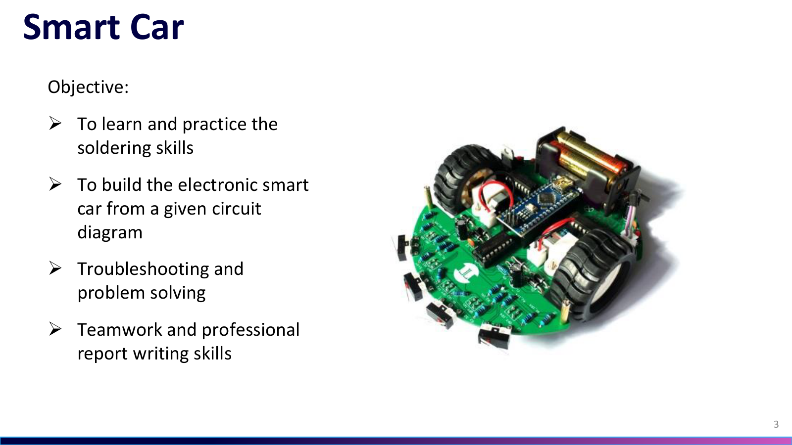
From Soldering to Troubleshooting从焊接走到故障排查
The course frame separates four aims. These were to practise soldering, build the car from the given circuit, troubleshoot problems, and work as a team while writing a professional report.课程把目标拆成四项。练习焊接,按给定电路完成小车装配,开展故障排查与问题解决,并以团队协作完成专业报告。
LM7805 Sets the 5 V RailLM7805 建立 5 V 电源轨
The course slide's schematic places 100 µF and 0.01 µF capacitors on both sides of the LM7805 and labels a 5 V output, linking the regulator stage to supply filtering.课件页原理图在 LM7805 输入、输出两侧各放置 100 µF 与 0.01 µF 电容,并标出 5 V 输出,把稳压级与电源滤波联系起来。
Reflection, Collision, and Wheel Speed反射、碰撞与轮速
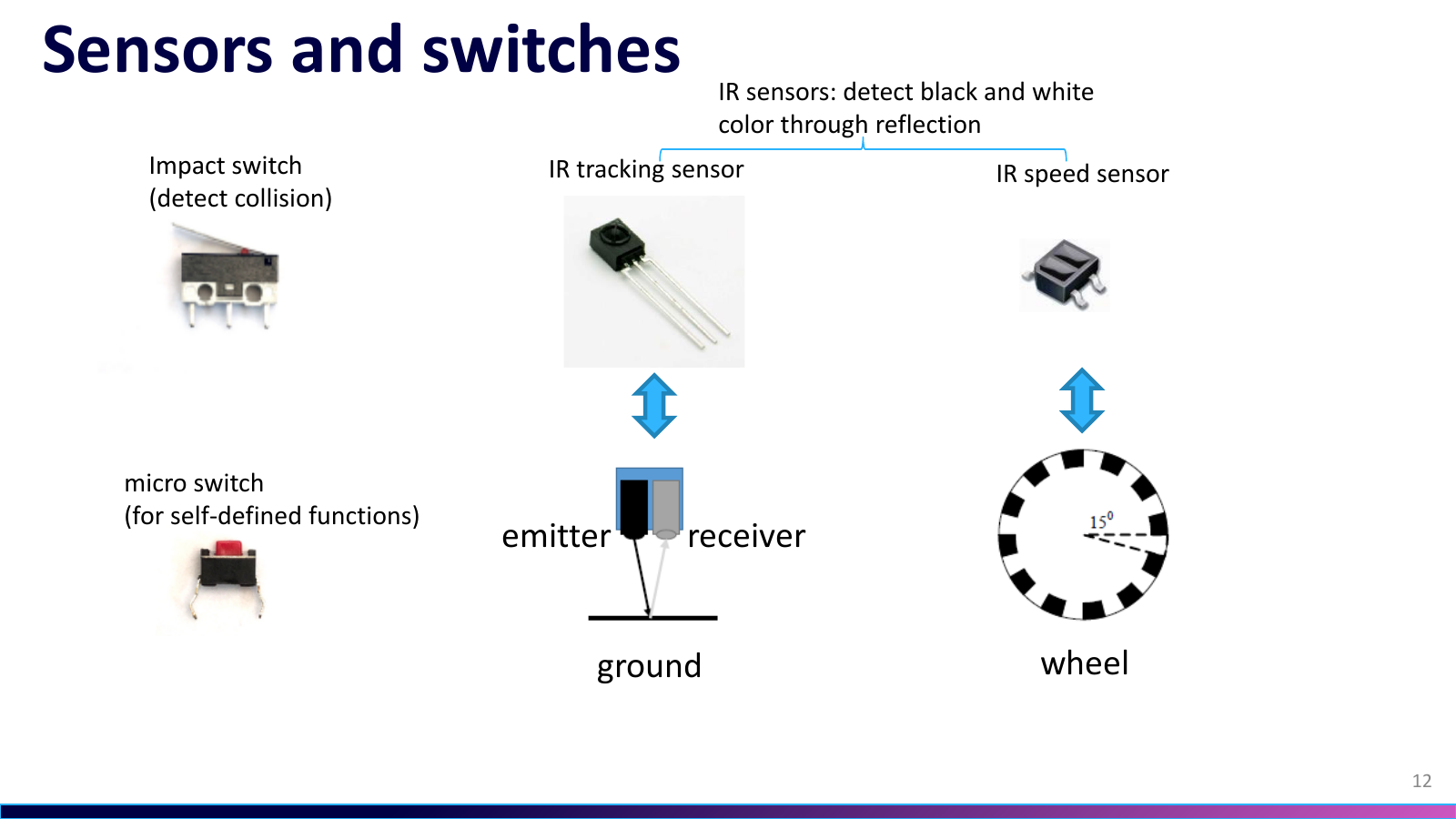
The course slide separates contact inputs from optical ones. An impact switch and a key provide contact inputs, an emitter-receiver pair tracks black and white, and an IR speed sensor reads a striped wheel.课件页把接触输入与光学输入分开。碰撞开关与按键负责触发,收发一体的红外对管辨别黑白,条纹轮盘则由红外测速传感器读取。
Fourteen Inputs, One Serial Read Path十四路输入,一条串行读取路径
The course slide counts six collision switches, six IR channels, and two keys as fourteen inputs; its parallel-in/serial-out model explains why the kit cascades two 74HC165s before the controller.课件页把六个碰撞开关、六路红外和两个按键合计为十四路输入;并入串出的模型解释了套件为何在主控前级联两颗 74HC165。
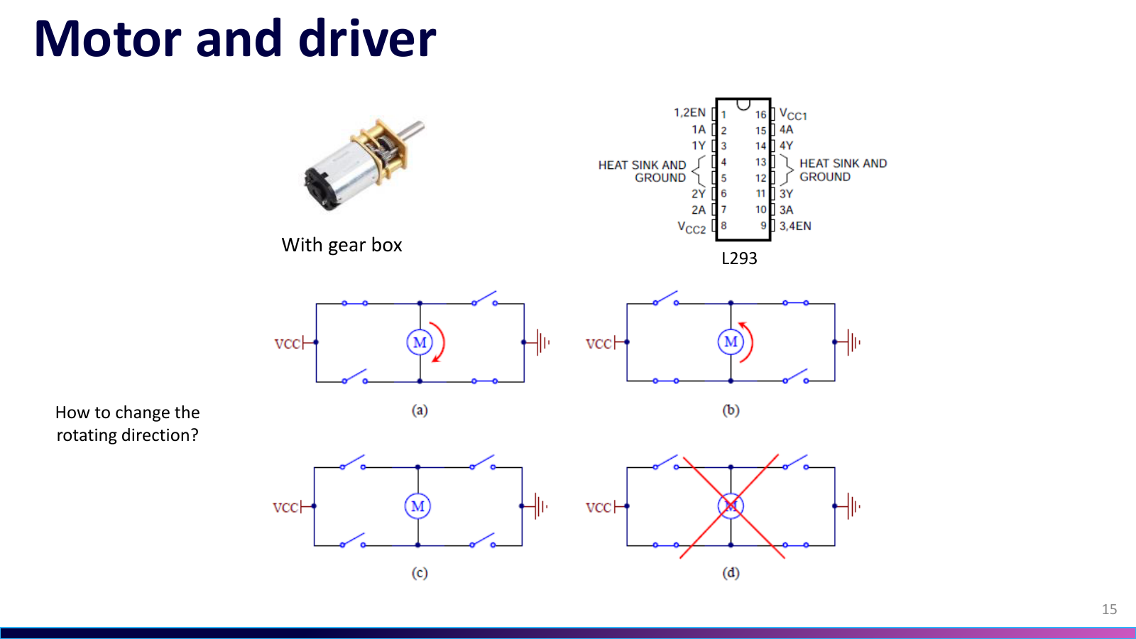
L293 Reverses the Geared MotorsL293 让减速电机正反转
On the course slide, the H-bridge sketches show how reversing the applied polarity changes motor direction; L293 packages that drive stage between the controller and two geared motors.课件页中的 H 桥示意图说明反转施加极性会改变电机方向;L293 把这一级驱动封装在控制器与两只减速电机之间。
Duty Cycle Sets Average Motor Drive占空比设定电机平均驱动
The course slide's 50% and 80% pulse trains, plus 10/50/90% examples, show how duty cycle changes the average drive applied to a motor; the project code then adjusts the left- and right-wheel PWM commands separately.课件页用 50% 与 80% 脉冲列和 10/50/90% 示例说明占空比如何改变施加到电机的平均驱动;项目代码随后分别调整左右轮的 PWM 指令。
Six Tests Before Full Line Tracking完整循迹前的六项测试
The course slide prescribes separate checks for LED, keys, collision switches, IR tracking channels, motors, and IR speed sensing; the supplied code also offered variants with and without the RGB LED.课件页规定逐项检查 LED、按键、碰撞开关、红外循迹通道、电机和红外测速;配套代码还提供带 RGB LED 与不带 LED 两种版本。
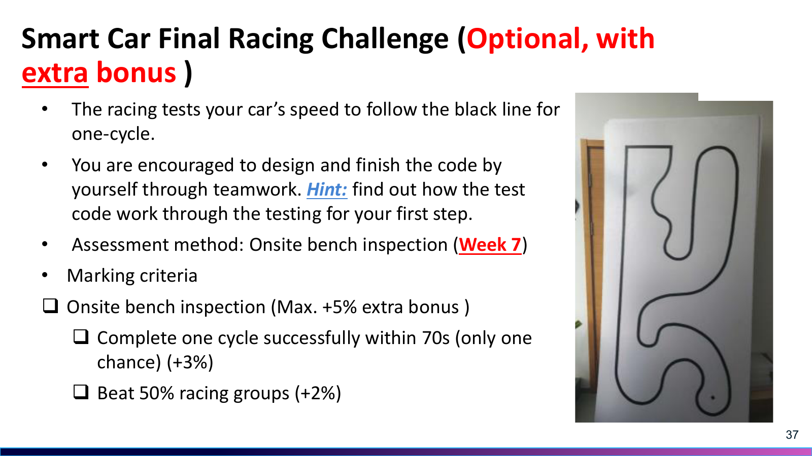
One Lap Brings the Signal Chain Together一圈赛道把整条链路接起来
The optional course slide asks the car to follow one black-line lap, awarding a 3% bonus within 70 s and another 2% for beating half the groups; the project record later reports a top-5% finish.可选挑战课件页要求小车沿黑线跑完一圈。70 秒内完成可获 3% 额外加分,超过半数小组再获 2%;项目记录显示这台车最终进入圈速前 5%。