2026-05-06
Juanyun AC Unit Control Board卷云外机板 V2.0 / V2.1 开发笔记
Notes on the AC unit control board split into main, power, and interaction PCBs with compressor, fan, sensor, OLED, Wi-Fi, and EEV interfaces.卷云外机板 V2.0/V2.1 整理:从单板需求扩展到主控板、分电板、交互板三块 PCB,覆盖压缩机、风扇、传感器、OLED、Wi-Fi 和电子膨胀阀接口。
Starting Point起点
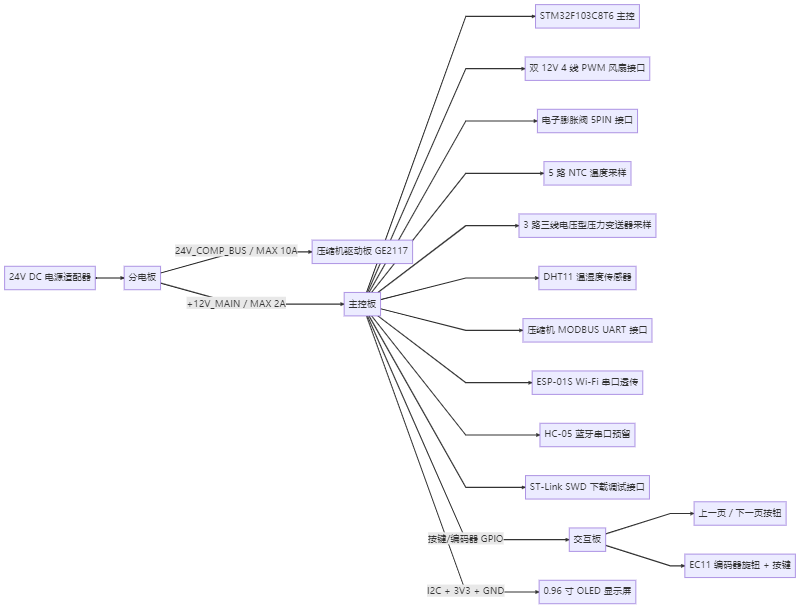
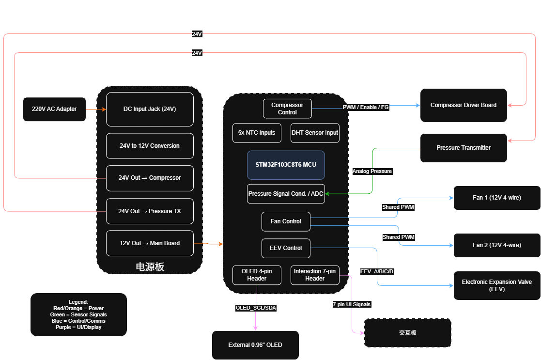
The AC unit control-board line felt crowded from the beginning, but it could not be treated as a random pile of ports. The same board concept had to cover 24 V input, 12 V fan power, the compressor driver board, electronic expansion valve, NTC, DHT, pressure transmitter, OLED, encoder, and reserved Wi-Fi. If I simply drew every connector onto one PCB, it would look busy, but later integration would almost certainly become painful.
卷云外机板这条线一开始给人的感觉就是东西很多,但不能乱。24 V 输入、12 V 风扇、压缩机驱动板、电子膨胀阀、NTC、DHT、压力变送器、OLED、编码器、Wi-Fi 预留,全都挤在一个“外机板”的概念里面。如果只是把接口一股脑画到板子上,看起来像是在干活,实际上后面联调的时候一定会出事。
真正麻烦的不是元件数量,而是这些接口彼此影响。V2.0 更像把核心链路跑通,V2.1 开始拆成主控板、分电板、交互板三块板。这个变化挺关键:板子不是把元件堆上去就结束,更多是在拆电源、接口、调试和装配约束。
Board-Splitting Logic拆板思路
If I followed a student-demo mindset, I might have stopped at "it can run." But this external unit board was not a small demo. It needed to connect compressor, fan, sensors, and user interaction, while still leaving firmware room for debugging. So I started reading the requirement as several separate questions: how power enters, how interfaces are divided, which signals cross boards, which later software can measure, which ports are only reserved, and where noise or high current needs extra care.
如果只按学生项目的思路,可能会觉得“能跑就行”。但外机板不是一个小 demo,它要接压缩机、风扇、传感器和用户交互,还要给固件留调试空间。于是需求被拆成几块看:电源怎么走,接口怎么分,哪些东西要跨板,哪些信号后续软件能测,哪些接口只是预留,哪些地方要小心噪声和大电流。
为什么 V2.1 要拆三块板,不能一块板解决?
一块板当然也能画,但问题会集中在一起。大电流、电源分配、用户按键、OLED、传感器输入、调试接口全挤在一起,后面改一个接口可能影响一片。拆成主控、分电、交互之后,问题更容易定位:电源归电源,交互归交互,MCU 周围的信号也少一点被大电流路径打扰。
Records Still Missing还要补的记录
The next useful records are not more pretty renders, but the evidence that explains how the board changed and how it behaves during bring-up.
- Organize the V2.0 / V2.1 system diagrams, PCB renders, and three-board split relationship.
- Explain the responsibilities of the main board, power board, and interaction board.
- Write down the interface risks for the compressor, fan, pressure transmitter, and electronic expansion valve.
- Add physical photos, power-on records, and version comparisons later so the page does not stop at "there are many files."
- 把 V2.0 / V2.1 的系统框图、PCB 渲染图和三板拆分关系整理出来。
- 把主控板、分电板、交互板各自承担的职责说清楚。
- 把压缩机、风扇、压力变送器、电子膨胀阀这些接口风险写进笔记。
- 后续补实物照片、上电记录和版本对比,不要让页面只停留在“文件很多”的状态。
Files And Screenshots文件和截图
- V2.0 system block
- V1.0 / V2.0 hardware revision archive
- V2.1 system block
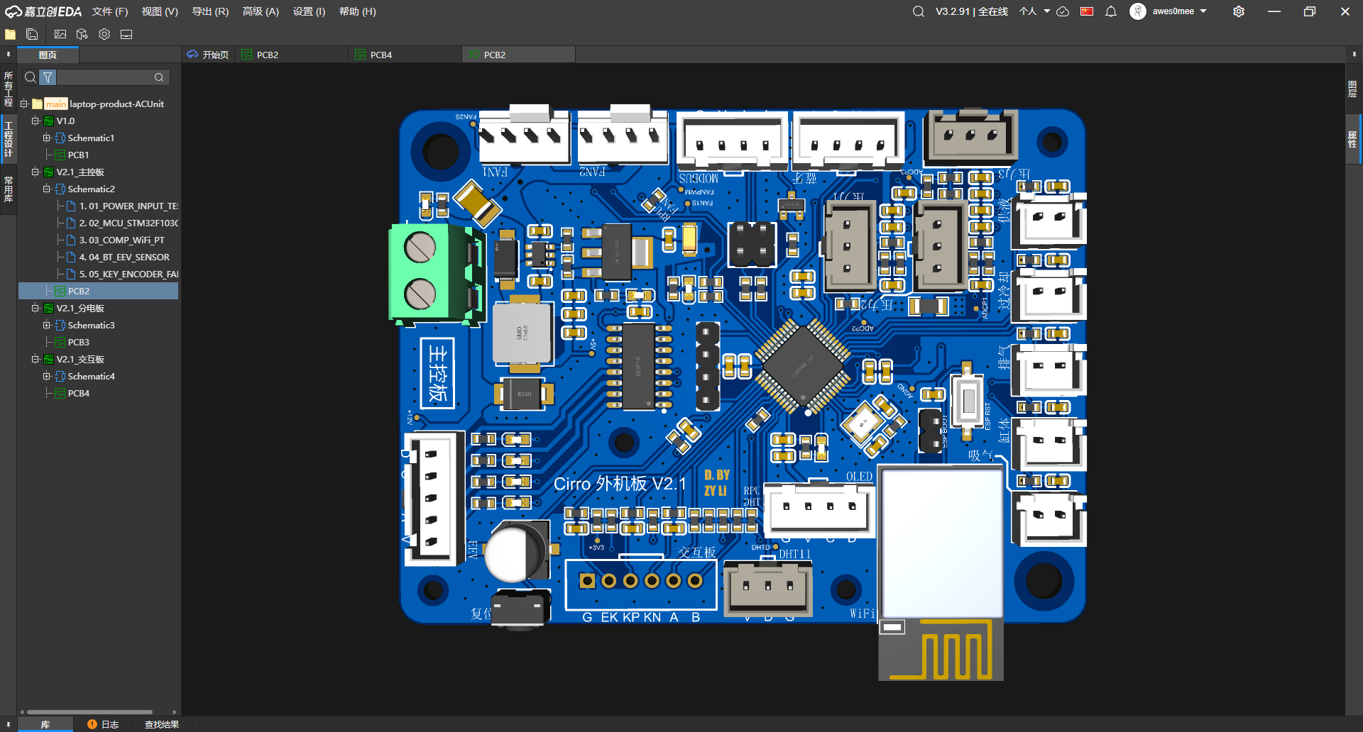
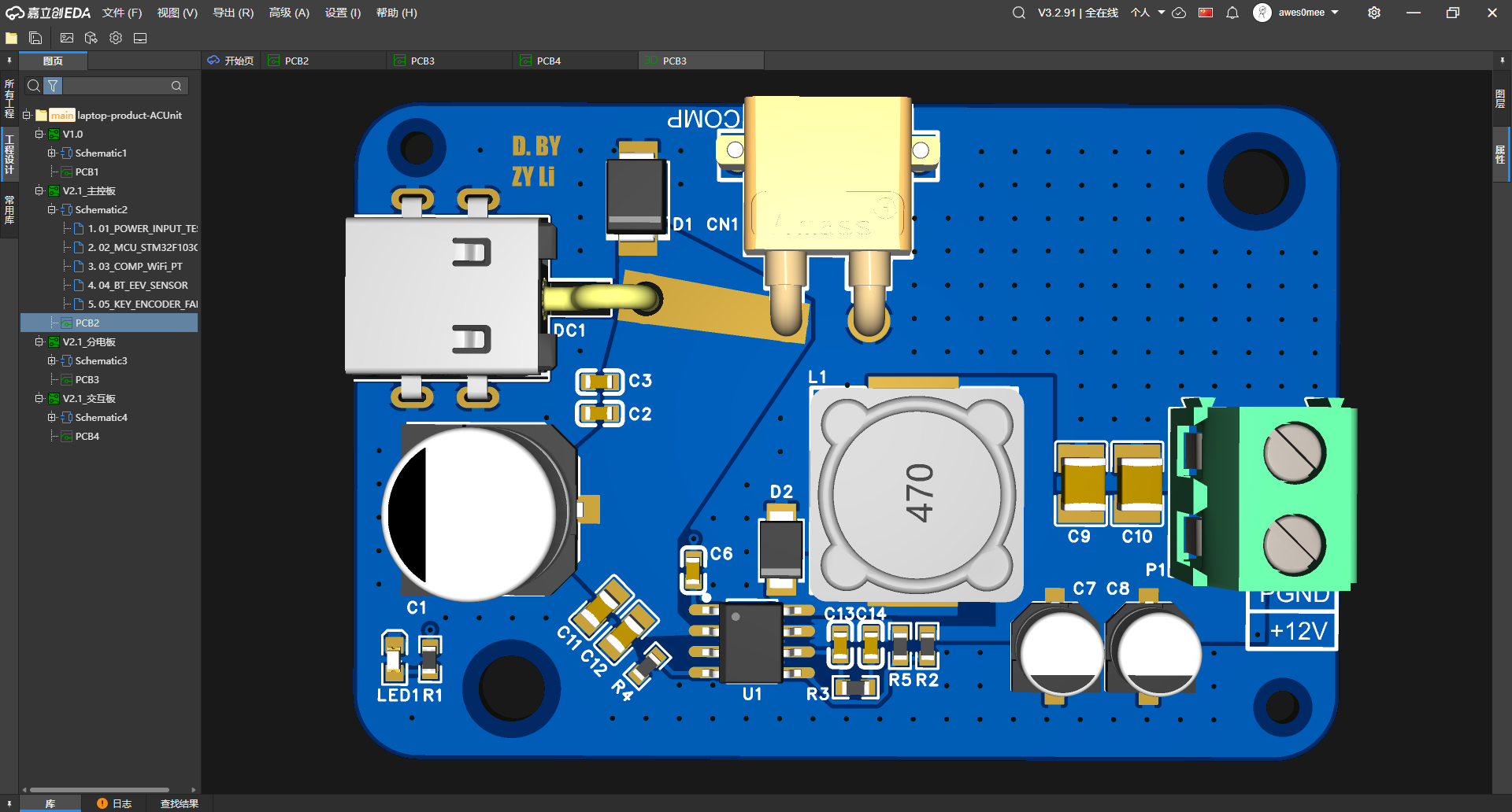
- V2.1 main board front render
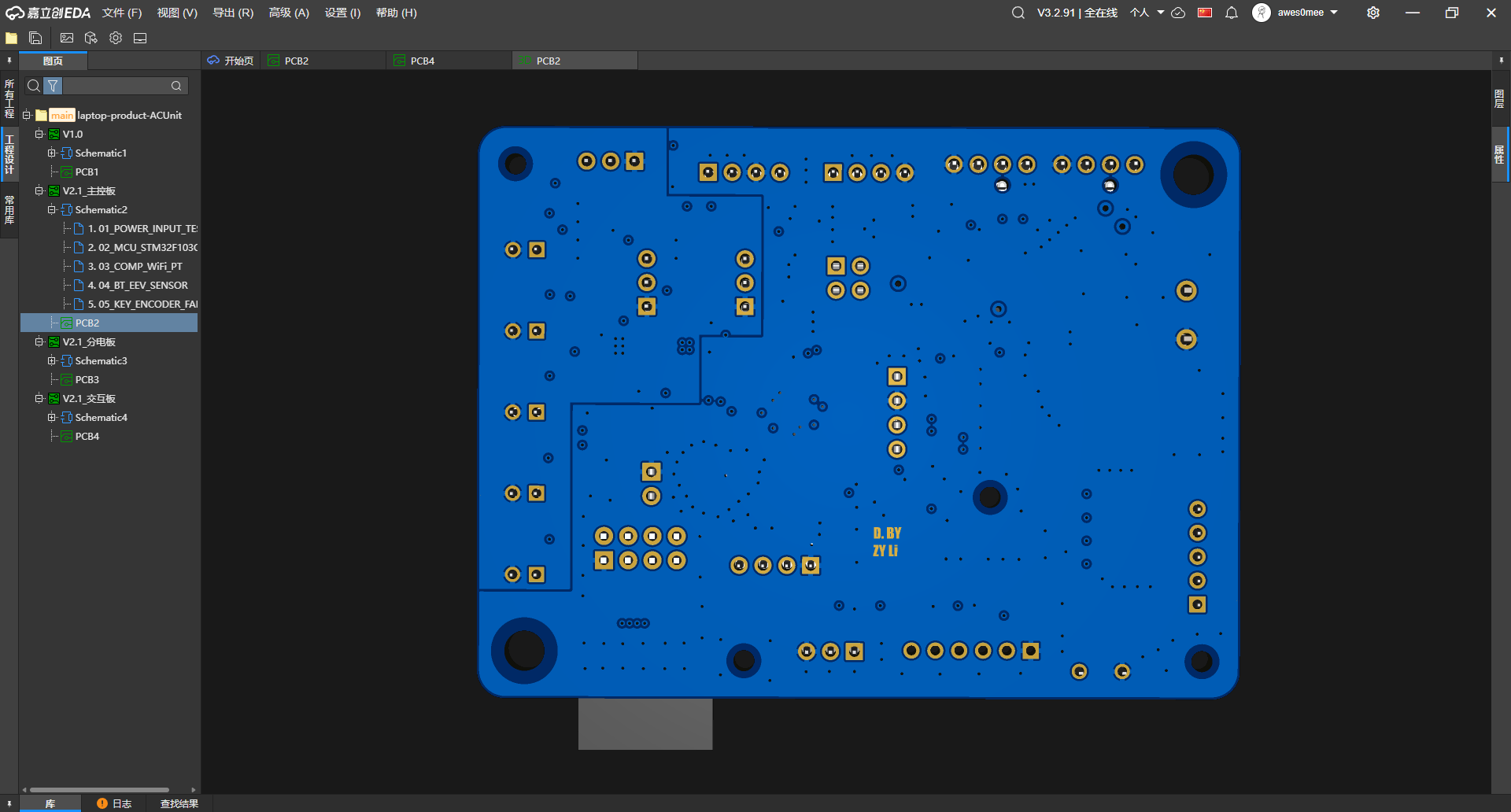
- V2.1 main board back render
- V2.1 power board front render
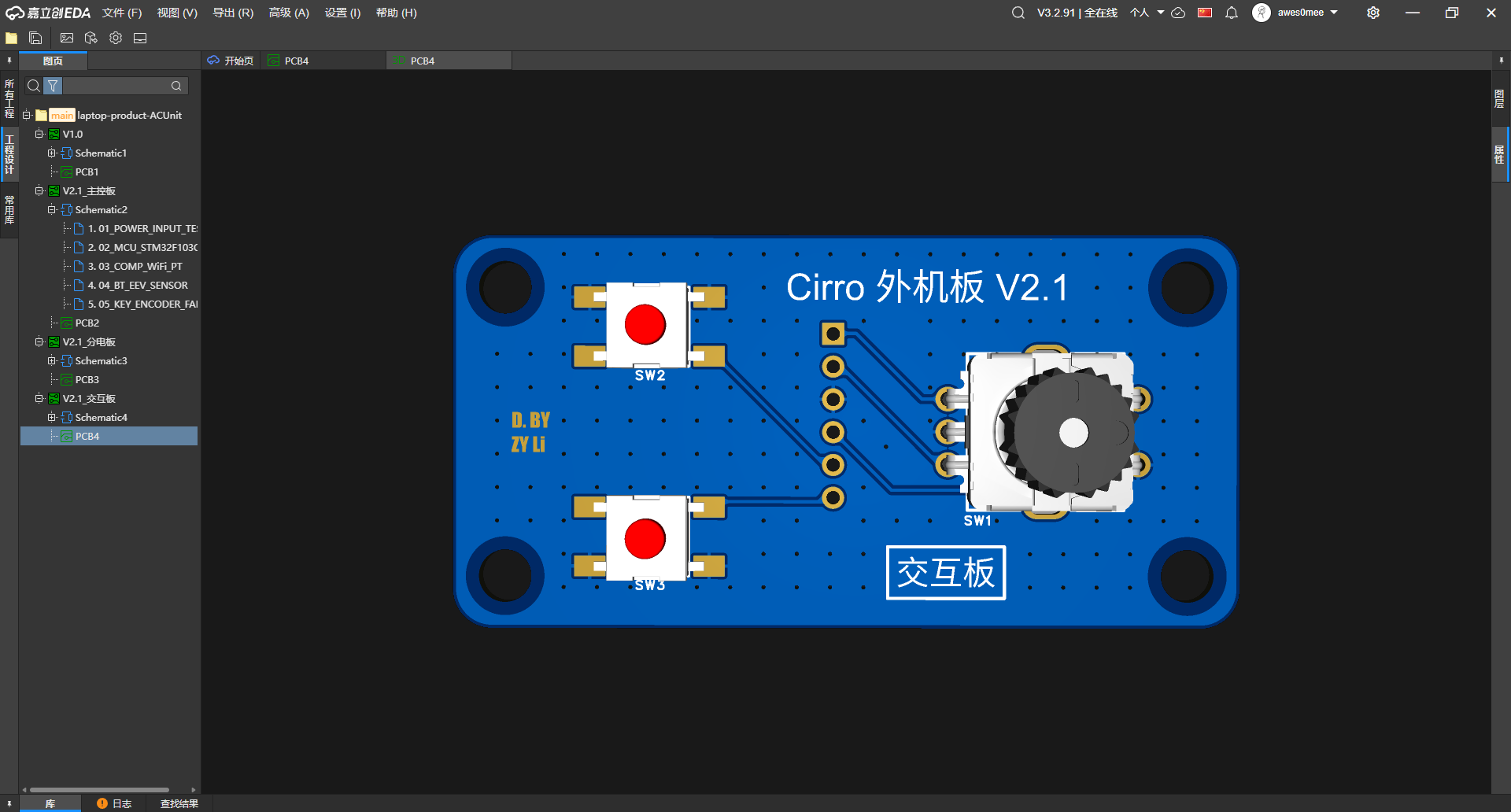
- V2.1 interaction board front render
Current Writing Boundary现在的写法
This line keeps the board-level structure and system-splitting record, but does not publish Gerber files, schematics, BOM, placement coordinates, or source downloads. The next stronger evidence should be power-on checks, interface tests, and revision comparisons. Only when those debugging records catch up will the external-unit board be more than a few clean render images.
这条线保留板级结构和系统拆分的记录,不放 Gerber、原理图、BOM、贴片坐标或源码下载。后面更该补的是上电检查、接口测试和版本对比。只有这些调试记录跟上,外机板才不只是几张漂亮渲染图。