

2026-05-06
Comparing ACUnit V2.0 and V2.1 System DiagramsACUnit V2.0 与 V2.1 系统框图对比
A comparison of the V2.0 routed block diagram and V2.1 interface mind map, limited to visible connections, labels, and unanswered revision questions.比较 V2.0 连线框图与 V2.1 接口思维图,只讨论可见连接、标签,以及两张图没有回答的版本问题。
V2.0 Power and Signal ConnectionsV2.0 电源与信号连接
The earlier public image carries its own title: Cirro V2.0 AC Unit Control System. It already contains three board blocks. The power board accepts the 24 V input and branches power toward the compressor, pressure transmitter, and main board. The main board collects sensing, fan, compressor, EEV, OLED, and interaction functions, while colored lines mark what crosses toward external loads and the interaction board.
较早的一张公开图在画面里直接写着 Cirro V2.0 AC Unit Control System,而且已经包含三块板。分电板接收 24 V 输入,把电源分往压缩机、压力变送器与主控板;主控板收拢传感、风扇、压缩机、EEV、OLED 与交互功能,再用彩色连线标出哪些信号跨向外部负载和交互板。
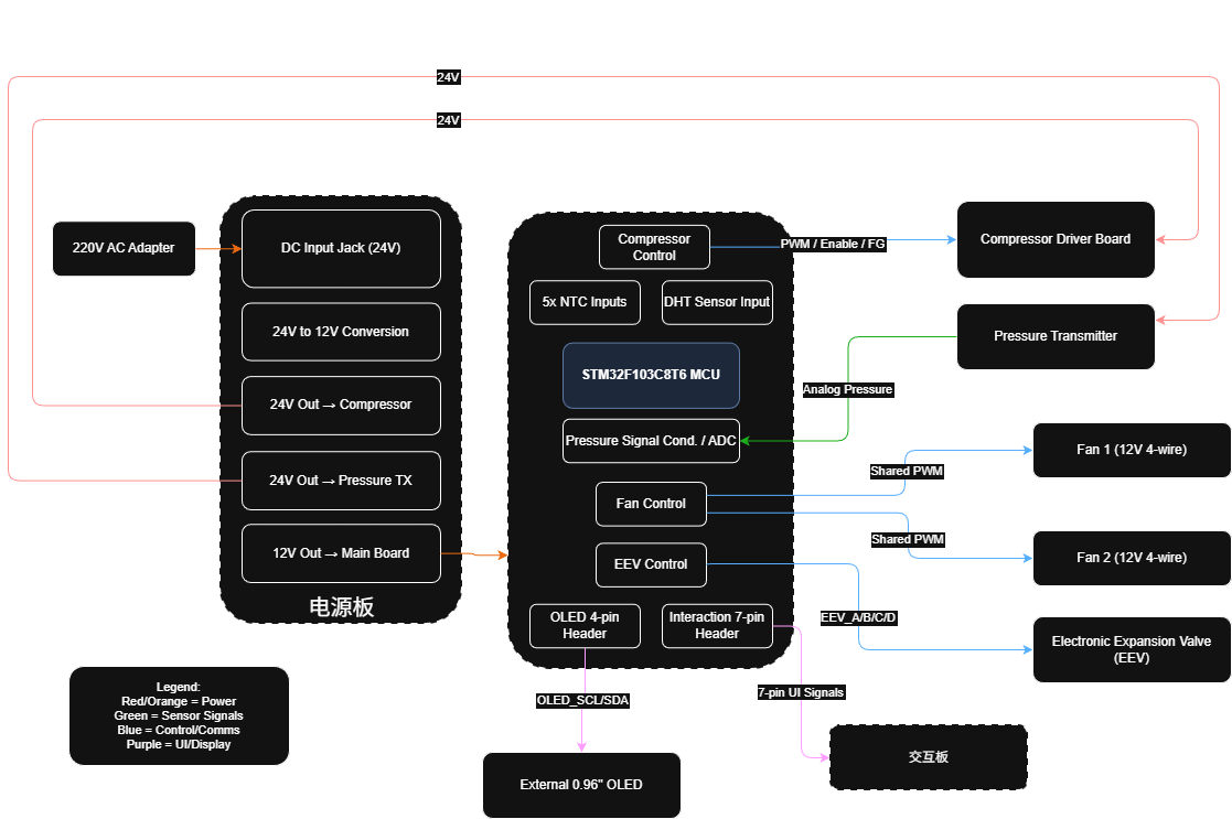
This drawing is route-oriented. Its legend separates power, sensor, control/communication, and UI/display paths, while arrow direction and line labels carry much of the explanation. A reader can follow Analog Pressure, Shared PWM, EEV_A/B/C/D, OLED_SCL/SDA, and the seven-pin UI link without seeing a PCB.
这张图偏向“沿线追踪”。图例把电源、传感、控制 / 通信、UI / 显示分色,箭头方向与线名承担了大部分说明。即使不看 PCB,也能顺着 Analog Pressure、Shared PWM、EEV_A/B/C/D、OLED_SCL/SDA 和七针 UI 连接一路读下去。
V2.1 Interface DiagramV2.1 接口框图
The other image is a Chinese mind map. It starts with the power board and main board, then fans outward into labeled interfaces: two power buses, STM32F103C8T6, two PWM fans, a five-pin EEV connector, five NTC channels, a linear pressure-sensor input, DHT11, compressor UART, Wi-Fi, Bluetooth, SWD, interaction inputs, and an OLED branch.
另一张图是一棵中文思维图:从分电板与主控板开始,向外展开两条电源总线、STM32F103C8T6、两把 PWM 风扇、五针 EEV、五路 NTC、线性压力传感器输入、DHT11、压缩机 UART、Wi-Fi、蓝牙、SWD、交互输入与 OLED 支路。
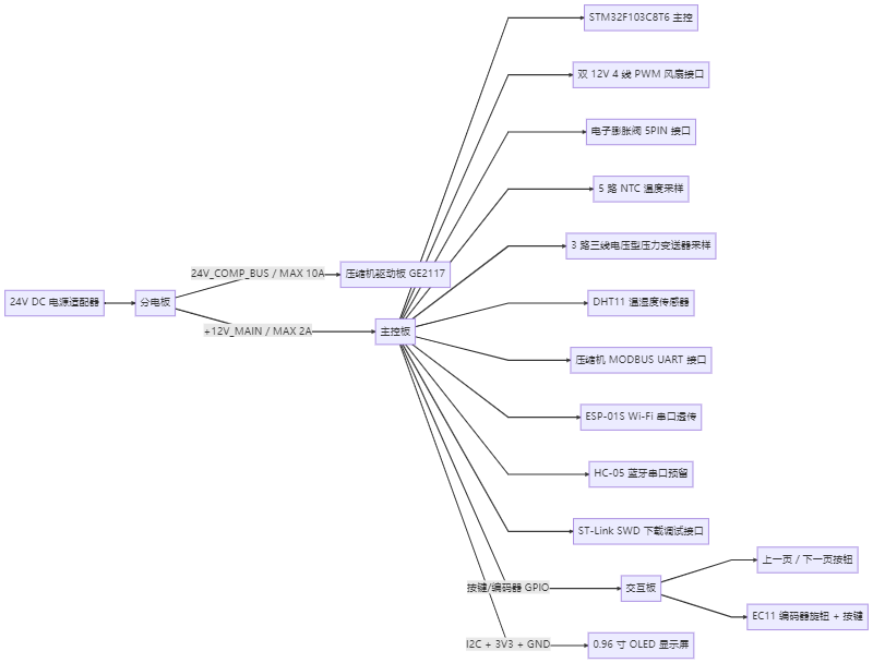
This version is inventory-oriented. It gives each interface its own branch, but most connections no longer carry the directional detail or color categories visible in V2.0. The three-board split is therefore not a V2.1 invention; it is visible in both images, expressed in two different visual grammars.
这张图偏向“逐项清点”。每个接口都有自己的分支,但多数连接不再保留 V2.0 那样的方向细节与颜色分类。因此,三板拆分并不是 V2.1 才突然出现的东西;两张图里都能看到它,只是用了两套不同的图形语法。
Diagram Comparison and Revision Records框图对比与改版记录
What changed visibly is the emphasis: routes and signal categories in V2.0, interface breadth and Chinese labels in V2.1. Neither image records a change request, review comment, electrical failure, mechanical constraint, fabrication result, or bring-up outcome. It would be tempting to turn the cleaner inventory into a story of design maturity, but that story is not inside these artifacts.
真正可见的变化只是侧重点:V2.0 看连线与信号类别,V2.1 看接口广度与中文标签。两张图都没有改版需求、评审意见、电气故障、机械约束、制造结果或 bring-up 结论。面对一张更容易清点的图,很容易顺手写成“设计成熟了”;可这段故事并不在材料里。
A stronger revision archive would pair each drawing with a dated change note and the board or test record affected by that change. Until those records appear, the safest comparison is also the most useful one: these are two documented views of a three-board ACUnit system, not a reconstructed development timeline.
更完整的版本归档应当把每张图与带日期的修改说明、受影响板卡或测试记录配在一起。在那些记录出现之前,最稳妥也最有用的结论就是:这是同一套三板 ACUnit 系统的两种已归档视图,不是一条被补写出来的开发时间线。