

Cirro Phase-Change Cooling Controllers卷云相变散热器控制系统
At Juanyun, I independently completed BaseUnit and three-board ACUnit hardware, firmware, and integration, then continued into automatic control and maintenance. The company team performed the later refrigeration tests.在卷云实习期间,我独立完成 BaseUnit 与三板 ACUnit 的硬件、固件和整机联调,随后继续参与自动控制与维护。后期完整制冷测试由公司团队执行。
- Timeline时间线
- 2025.11 - 2026.052025.11 - 2026.05
- Status状态
- Completed Internship Project已完成实习项目
- Stack技术栈
- STM32PCBC/C++ThermalFirmwareControlBring-up

Two Controllers两套控制器
The phase-change cooler I worked on during my Juanyun internship is a small air-conditioning system feeding a laptop. An external compressor and refrigeration loop produce cold air, and a base directs it into the laptop intake. My responsibility was to make the base and external-unit hardware, firmware, and PC tool work together, then hand the system over for continued testing.
在卷云实习时,我做的这套相变散热器,可以理解为给笔记本送冷风的小空调。外机用压缩机和制冷回路产生冷风,底座把风送入笔记本进风口。我的工作是让底座与外机的硬件、固件和电脑端工具一起运行,最后交给团队继续测试。
I first completed the BaseUnit hardware, firmware, and real-machine bring-up independently. Sitting under the laptop, it coordinated two temperature/humidity channels, presence detection, a fan, OLED, buttons, Bluetooth, and saved settings. Familiar components became a combined set of questions: whether the fan should run while off, whether a held button should trigger again, and which setting should survive a restart. Getting this smaller controller working gave me the confidence to take on the ACUnit.
我先独立完成了 BaseUnit 的硬件、固件和实机联调。它放在笔记本下面,要处理两路温湿度、在位检测、风扇、OLED、按键、蓝牙和参数保存。器件看起来都熟悉,但放到同一台设备里,关机时风扇该不该转、按键按住会不会重复触发、重启后恢复哪个设定,都得一起考虑。先做通这套较小的控制器,我才有把握继续处理 ACUnit。
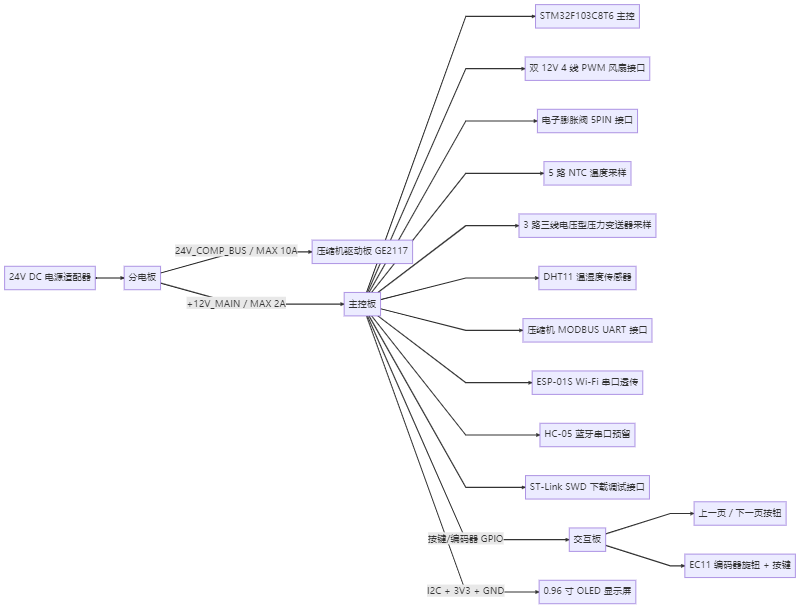
The external ACUnit uses power, main-control, and interaction boards to connect the compressor driver, electronic expansion valve (EEV), fans, pressure and temperature sensing, OLED, local inputs, and wireless interfaces. I independently handled all three schematics and PCBs, manufacturing preparation, assembly and soldering, firmware, staged power-up, integration, and the V2.1 development SOP.
外机 ACUnit 分为分电板、主控板和交互板,要接压缩机驱动板、EEV 电子膨胀阀、风扇、压力与温度传感、OLED、本地输入及无线接口。三块 PCB 的原理图、布局、制造准备、装配焊接、固件、分阶段上电与整机联调,以及 V2.1 开发 SOP,都由我独立完成。
Firmware Planning固件规划
I planned the App, Service, and BSP responsibilities before implementing the growing set of interfaces. I also estimated a schedule at 1, 10, 100, 500, and 2000 ms for EEV stepping, input feedback, communications and sensing, display updates, and slower environmental reads. Responsibilities continued to evolve as I decomposed the functions, but the basic structure preceded the firmware implementation.
接口多起来后,我先规划 App、Service 与 BSP 的职责,再写具体功能。调度也提前按 1、10、100、500、2000 ms 分档估算,让 EEV 步进、输入反馈、通信传感、显示和慢速环境读取各有安排。实现时继续拆分和调整职责,基本结构在动笔写固件前就已经确定。
I knew RTOS concepts without having used one on a real project, and wanted this work to test my bare-metal fundamentals. The STM32F103 had limited resources, and explicit cooperative scheduling and state machines could still organize this workload. I split EEV homing, communication waits, and retries into incremental states, returning the CPU to the main loop between actions. Slow DHT reads waited while the EEV was busy. Handling these waits was an important part of the exercise for me.
我知道 RTOS 的概念,却没有实际项目经验,也想借这次工作检验自己的裸机基础。STM32F103 资源有限,这套并发仍能用协作式调度与状态机组织。我把 EEV 回零、通信等待与重试等过程拆成可以逐次推进的状态,在两次动作之间把 CPU 还给主循环;慢速 DHT 读取则避开 EEV 忙碌的时候。对我来说,能否处理好这些等待,正好是这次练习的重点。
Power-Up and Integration上电与联调
I checked the power board first, then connected the main and interaction boards, separating rail checks from peripheral tests. I measured 24.07 V at the 24 V input and bus, 12.03 V at the converted output, and about 18 mA of power-board no-load current. Main-board rails measured 12.03 V, 4.99 V, and 3.32 V.
我先查分电板,再接主控与交互,把电源和外设分开验证。24 V 输入与总线测得 24.07 V,变换输出 12.03 V,分电板空载电流约 18 mA;主控的三条电源轨分别为 12.03 V、4.99 V、3.32 V。
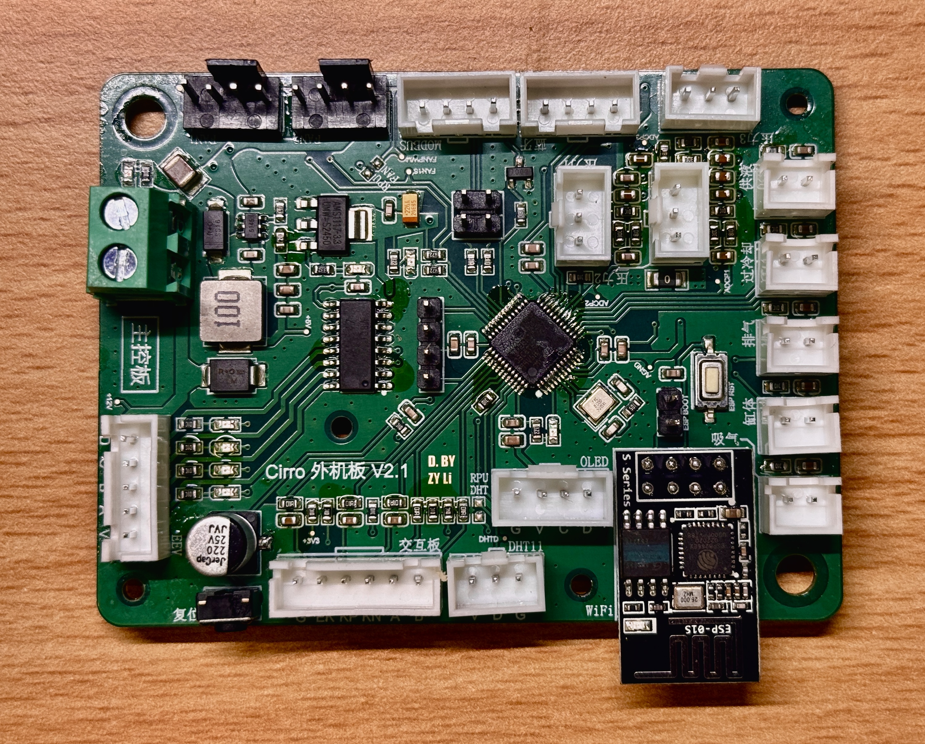
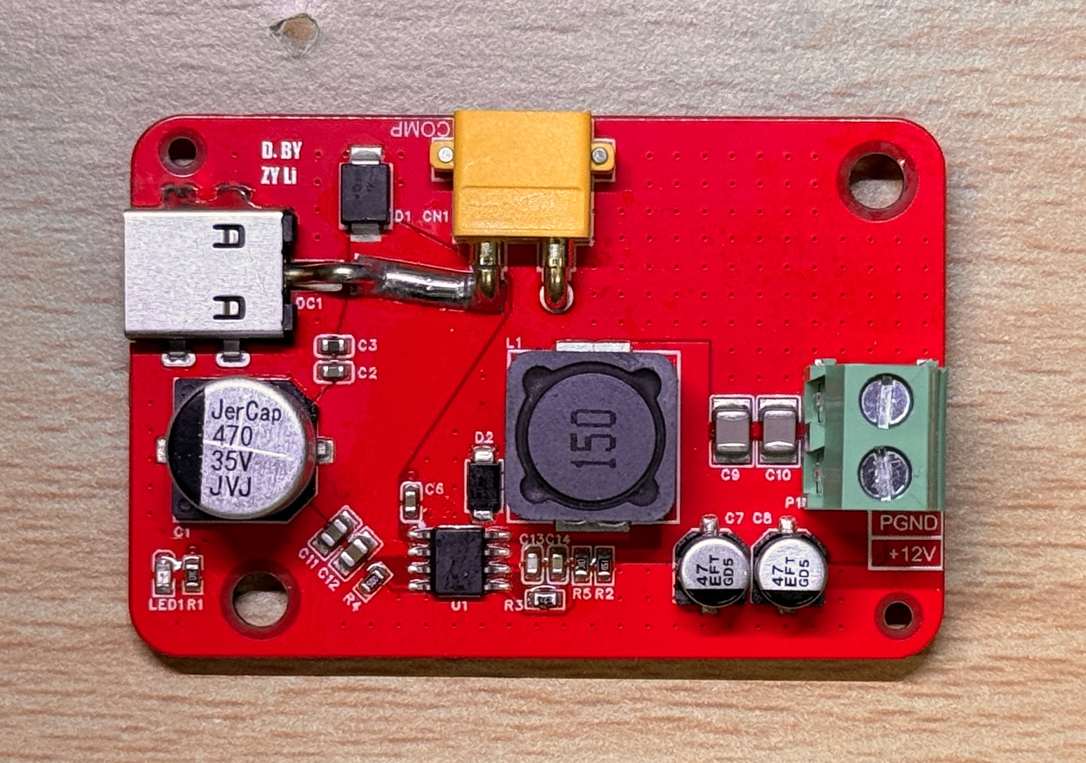
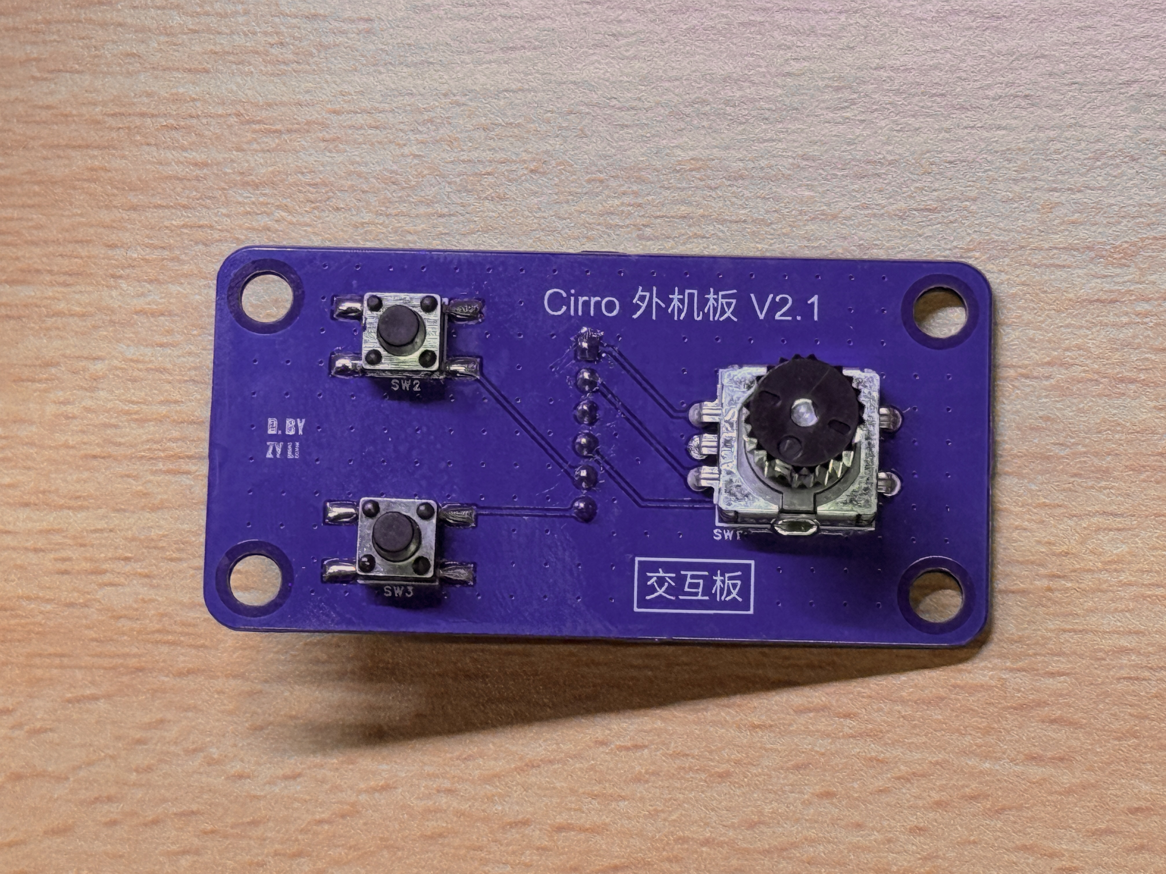
I then tested temperature sensing, fan PWM and TACH, EEV, ESP, OLED, interaction inputs, and basic compressor communication individually. The NTC read about 24.7°C against nearby references of roughly 24.8 to 24.9°C. The interaction board also had a cable-order mismatch, corrected by changing the wire order without another PCB spin. It also reminded me to check the connections between boards separately.
之后再逐项测试温度、风扇 PWM 与 TACH、EEV、ESP、OLED、交互输入和基础压缩机通信。NTC 当时约为 24.7°C,附近参考约为 24.8 到 24.9°C。交互板还遇到一次排线顺序不匹配,调整线序后恢复正常,不需要重新投板。这次异常也提醒我,板间连接需要单独核对。
Next I connected all three ACUnit boards, the compressor driver, compressor, supply, and PC. The ControlPanel began showing compressor state and data returned over Modbus alongside temperatures calculated from ADC readings. Interfaces I had checked separately were finally cooperating in one running system.
随后,我把三块 ACUnit 板、压缩机驱动板、压缩机、电源和电脑全部接起来。ControlPanel 开始显示 Modbus 返回的压缩机状态与数据,旁边还有由 ADC 读数换算出的温度。此前单独检查过的接口,终于在同一次运行里配合起来。
That felt extremely good. The boards I had designed, soldered, and programmed were controlling a real machine.
这种感觉太爽了。自己设计、焊接和编程的板子,真的在控制一台机器。
Automatic Control and Maintenance自动控制与维护
I continued working on the same project's production-line development. Manual valve, fan, and compressor commands remained available for testing, while automatic EEV and compressor decisions moved into a board-side core. The system gained STOP, QUIET, PERF, and ZERO modes, with sensor validity, superheat, pressure, and startup constraints taking precedence over ordinary temperature targets. The automatic-control note explains how those decisions affect the valve and compressor.
后续我继续参与同一项目的 production-line 开发。手动调阀、调风扇和发送压缩机指令保留为测试入口,EEV 与压缩机的自动决策则逐步进入板端核心。系统加入 STOP、QUIET、PERF、ZERO 模式,也把传感有效性、过热度、压力和启动约束放到普通温度目标之前。自动制冷控制笔记具体解释了这些判断怎样影响阀和压缩机。
During later maintenance, the ControlPanel gained trend plots, CSV export, Monitor and Debug logs, and separation between monitoring and direct control. Firmware added safer startup, data-validity checks, and clock fallback after HSE initialization failure.
在后续维护中,ControlPanel 逐渐增加了趋势图、CSV 导出、Monitor 与 Debug 日志,以及监测和直接控制的区分。固件也补充了安全启动、数据有效性检查和 HSE 初始化失败后的时钟回退。
The company team performed the later refrigeration tests. The boss and testers reported working telemetry, manual controls, QUIET, PERF, and ZERO modes, observable EEV superheat regulation and continuous compressor-speed changes, and triggers of low-superheat, negative-superheat, and high-condensing-pressure protection.
后来的实机制冷测试由公司团队完成。老板与测试人员反馈,遥测、手动控制、QUIET、PERF、ZERO 模式能够运行,观察到了 EEV 过热度控制与压缩机连续调速的变化,也触发过低过热度、负过热度和高冷凝压力保护。
After Handoff交付后的状态
The company also described a small trial involving more than ten campus students and faculty. It reported roughly 25 to 40 percent better performance in some sustained workloads, including large renders and AAA games, and one unit running continuously for over 150 hours. Cooling feedback was positive, but the size and poor portability remained practical drawbacks. The product did not reach mass production.
公司还转述过十余名校园师生参与的小规模试用,在大型渲染、3A 游戏等持续负载中,部分场景性能提高约 25% 到 40%;另有单台设备连续运行超过 150 小时。团队反馈制冷效果不错,占地大、便携性不足也始终是实际问题,产品最终没有量产。
My boss later joked that before I joined, opening the EEV involved moving a magnet around the valve by hand. Now testers could issue commands, read status, and continue their own work. I am grateful the team trusted an undergraduate with such a complete hardware and firmware assignment. Connecting it into a working system and handing it over was the most satisfying part of the placement.
老板后来开玩笑说,我来之前,他们开 EEV 还得拿磁铁绕着阀一点点吸着转。现在测试人员终于可以从界面发出指令、读到状态,继续推进自己的工作。我很感谢团队把这么完整的一套硬件与固件任务交给当时还在读本科的我。最后能把它接起来交出去,是这段实习里最让我满足的事。
Development Notes开发笔记
Debugging records and technical notes tied to the decisions and artifacts on this project page.与这个项目页面中的设计决策和工程材料直接关联的调试记录与技术笔记。
Public Project Files公开项目资料
Uploaded evidence served from the public asset folder. Use the file index to preview documents, source code, media, PDFs, and downloadable artifacts without leaving the page.这里列出已经上传到公开目录的项目证据。可以在左侧索引里选择文件,在右侧直接预览文档、源码、媒体、PDF 和可下载附件。
bldc-quiet-fan-bom.xlsx
Excel / 11.9 KB
Preview not available暂不支持预览
This file type is kept as a downloadable project artifact. Use the open button above to view it directly.这个文件类型会作为项目附件保留。可以使用右上角按钮直接打开原文件。
Related Media相关媒体
Board photos, schematic sheets, videos, and test captures that show this project at specific stages.展示这个项目具体阶段的板卡照片、原理图分页、视频和测试截图。
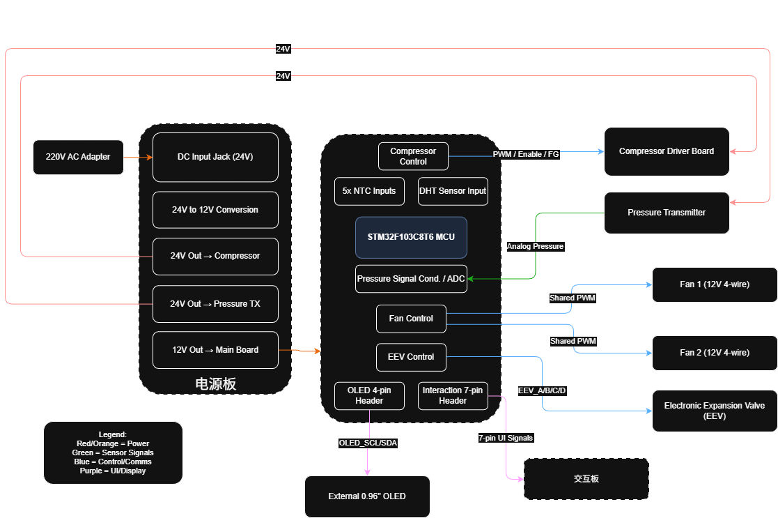
Power and signal routes in the V2.0 ACUnit diagramV2.0 ACUnit 图里的电源与信号路径
The titled V2.0 diagram traces power, sensing, control, display, and user-interface paths across power, main-control, and interaction boards.这张自带 V2.0 标题的图跨分电板、主控板与交互板,追踪电源、传感、控制、显示和用户交互路径。
V2.1 ACUnit interface mind mapV2.1 ACUnit 接口思维图
A Chinese branch map listing power buses, STM32, fan, EEV, sensor, UART, wireless, SWD, interaction, and OLED connections around three boards.中文分支图围绕三块板列出电源总线、STM32、风扇、EEV、传感器、UART、无线、SWD、交互与 OLED 连接。
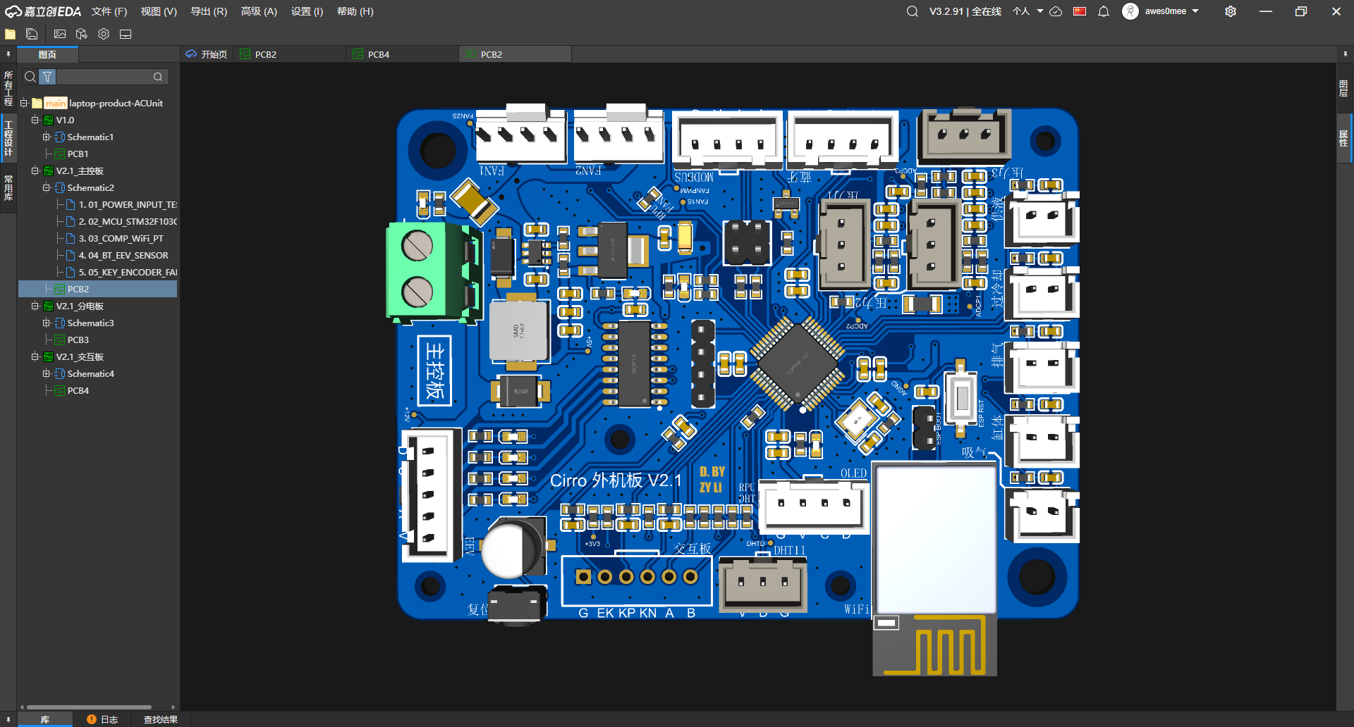
Connectors around the ACUnit main board围住 ACUnit 主控板的连接器
Front-side render with an STM32 package, labeled sensor and display headers, edge connectors, reset, and a Wi-Fi module position.正面渲染可见 STM32 封装、带标签的传感与显示排针、板边连接器、复位键和 Wi-Fi 模块位置。
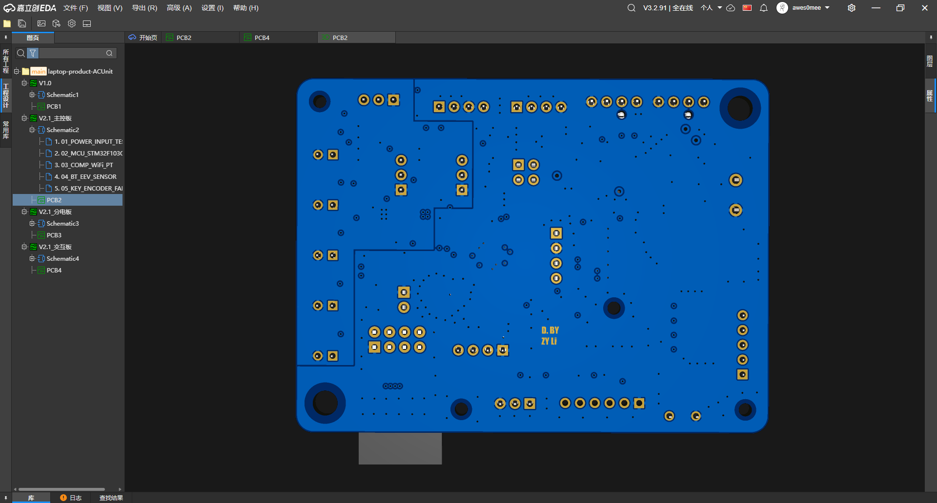
Main-board routing from the back从背面看主控板走线
The back render exposes mounting holes, through-hole pads, vias, and routing that the component-heavy front view hides.背面渲染露出安装孔、通孔焊盘、过孔与走线,补上器件密集正面看不到的部分。
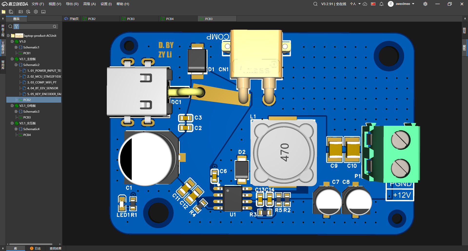
DC input and 12 V terminal on the power board分电板上的 DC 输入与 12 V 端子
Front render grouping a DC jack, blade fuse, conversion components, a 470-marked inductor, and the +12V/PGND screw terminal.正面渲染把 DC 插座、片式保险丝、变换器件、标着 470 的电感与 +12V/PGND 螺钉端子放在一起。
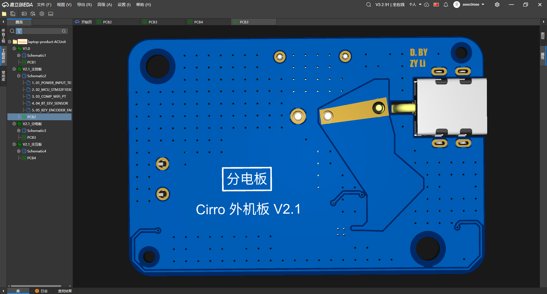
Wide copper on the power-board back分电板背面的宽铜箔
Back-side view of the same board, where broad copper shapes, mounting holes, and the DC-jack connection are visible without component clutter.同一块板的背面视角,宽铜箔、安装孔与 DC 插座连接不再被正面器件遮住。
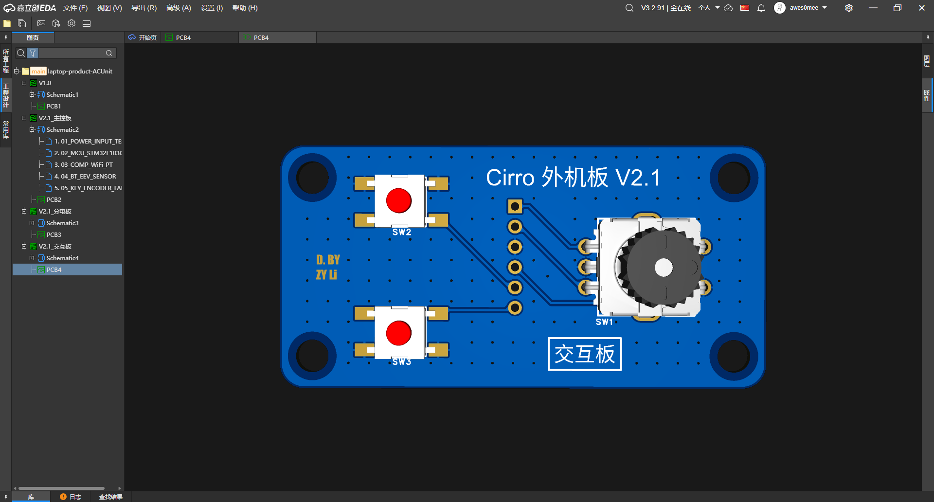
Encoder and two buttons on the interaction board交互板上的编码器与两个按键
The front render reduces the user-input surface to one rotary encoder, two push buttons, six header pads/holes, and four mounting holes.正面渲染把用户输入收在一只旋转编码器、两个按键、六个连接焊盘 / 孔与四个安装孔上。
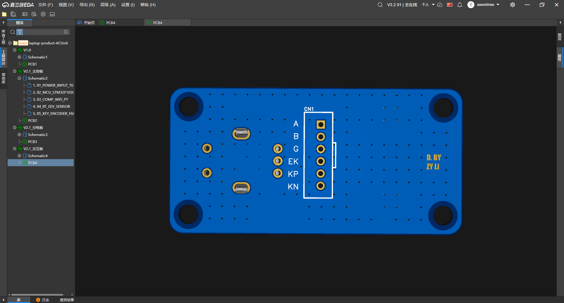
Interaction-header labels from the back从背面读交互板排针标签
The rear view makes the six header labels A, B, G, EK, KP, and KN legible beside the encoder and button footprints.背面视角让 A、B、G、EK、KP、KN 六个排针标签与编码器、按键焊盘的对应关系更清楚。
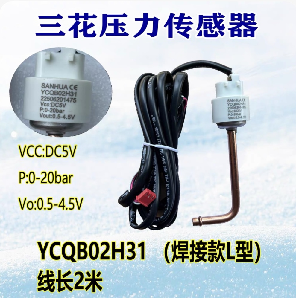
5 V pressure-sensor specification screenshot5 V 压力传感器规格截图
The product image labels a Sanhua YCQB02H31 with 5 V supply, 0-20 bar range, 0.5-4.5 V output, and a two-metre lead; it does not show selection or testing.产品图标注三花 YCQB02H31、5 V 供电、0-20 bar、0.5-4.5 V 输出和两米线长;画面不说明它已经选型或测试。
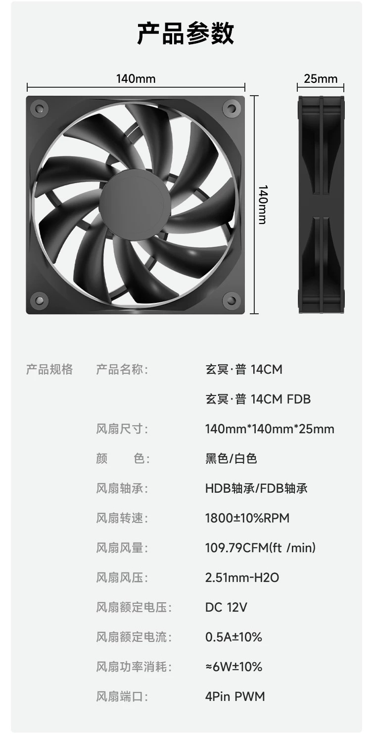
140 mm four-pin PWM fan specification screenshot140 mm 四针 PWM 风扇规格截图
The screenshot lists 140 x 140 x 25 mm, 12 V, 1800+/-10% RPM, and a four-pin PWM connector as candidate interface constraints, not measured platform results.截图列出 140 x 140 x 25 mm、12 V、1800+/-10% RPM 与四针 PWM 接口,可作候选约束,不能当作平台实测结果。
Populated V2.1 ACUnit main board完成装配的 V2.1 ACUnit 主控板
The assembled main board shows the populated STM32, edge connectors, ESP-01S module, and labeled sensor and control headers that had previously appeared only in renders.装配后的主控板实物可见 STM32、板边连接器、ESP-01S 模块,以及此前只出现在渲染图中的传感与控制接口。
Populated V2.1 ACUnit power board完成装配的 V2.1 ACUnit 分电板
The populated power board brings the DC input, fuse, conversion stage, terminal block, and board-level indicators into one workbench view.装配后的分电板把 DC 输入、保险丝、变换电路、接线端子和板上指示器件落到了同一张工作台实拍中。
Populated V2.1 ACUnit interaction board完成装配的 V2.1 ACUnit 交互板
The assembled interaction board shows the rotary encoder and two push buttons as soldered hardware rather than PCB-render placeholders.交互板实拍把旋转编码器与两个按键呈现为已经焊接完成的硬件,不再只是 PCB 渲染中的器件位置。
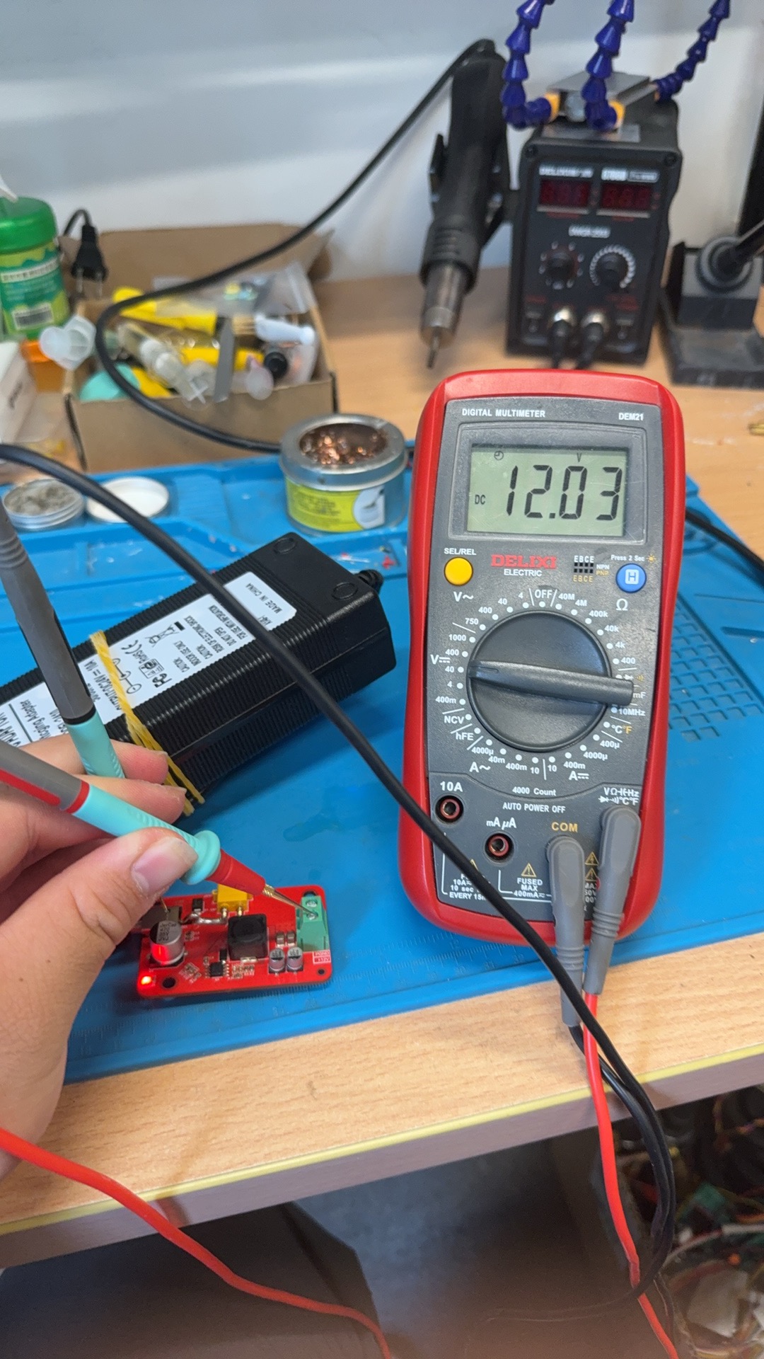
12 V reading during power-board bring-up分电板上电时的 12 V 测量
With the power board energized on the bench, the multimeter display reads 12.03 V during the recorded output check.分电板在工作台上通电后,万用表在这次输出检查中显示 12.03 V。
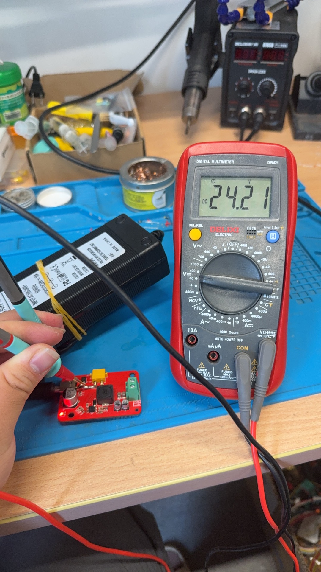
24 V reading during power-board bring-up分电板上电时的 24 V 测量
A second energized-board check records 24.21 V on the multimeter display; the accompanying development record provides the rail context.另一张上电检查照片记录了万用表显示的 24.21 V;具体测量节点由配套开发记录提供语境。
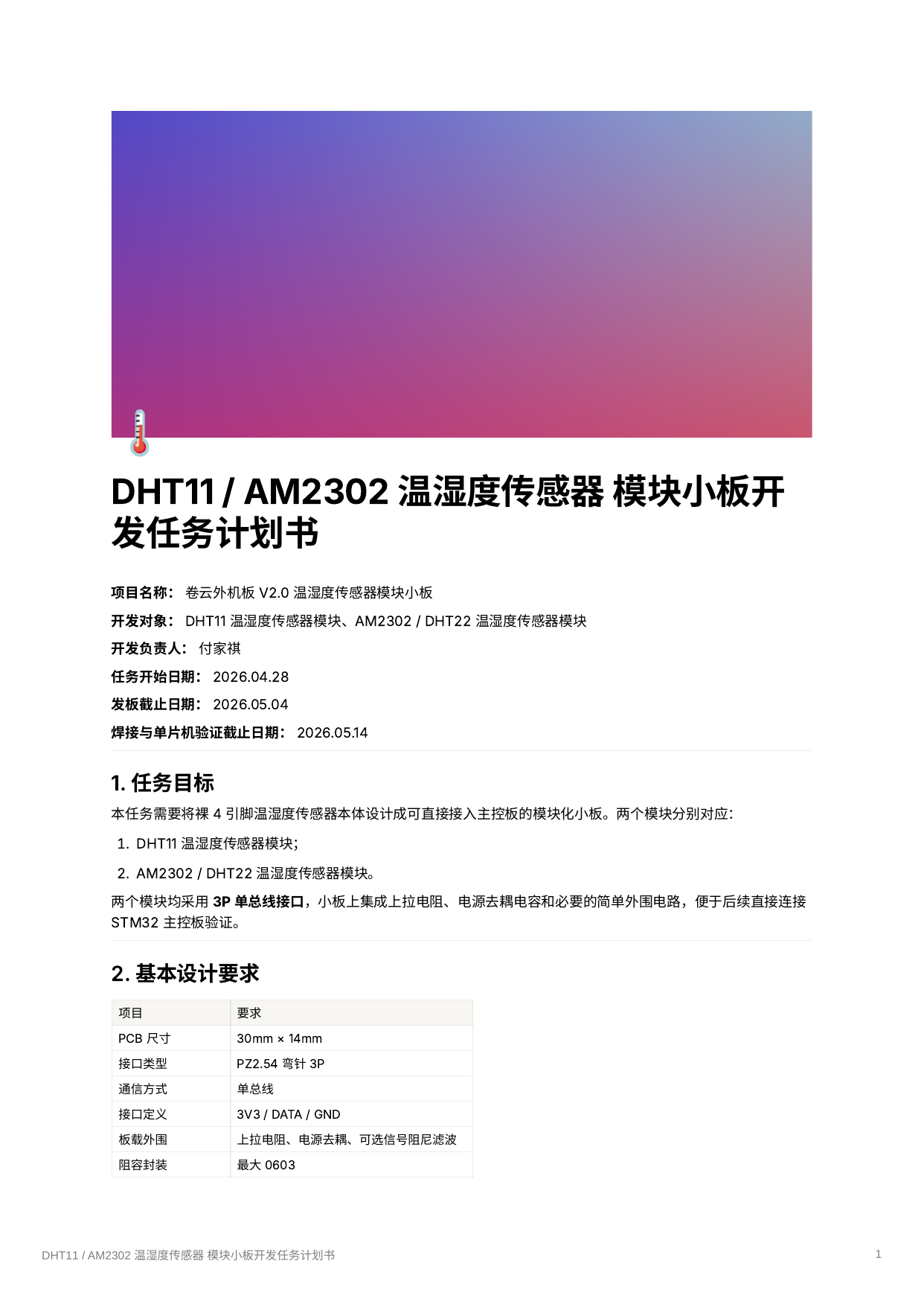
Six-page DHT11 / AM2302 board task plan六页 DHT11 / AM2302 小板任务计划
The cover belongs to an assigned plan for two sensor breakouts, with another development owner named and board, soldering, and MCU checks listed as later milestones in the plan.封面来自两种传感器小板的分配任务,署名另一位开发负责人,并在计划中把发板、焊接与 MCU 检查列为后续节点。

Cover image for the separate hardware SOP独立硬件 SOP 的封面图
This image marks the separate self-authored SOP preserved as its own note and PDF; the cover itself does not summarize the document.这张图指向以独立笔记与 PDF 保留的自写 SOP;单看封面并不能概括文档内容。

Cirro Tech archive cover卷云科技归档封面
A company logo and wordmark used to identify the Juanyun archive context; the mark is not presented as personal design work.用于标识卷云归档语境的公司 Logo 与字标,不把这套标识呈现为个人设计作品。
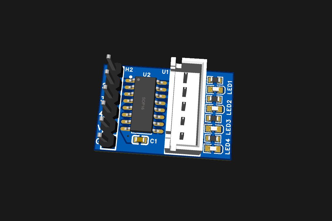
U2 package between the EEV headersEEV 接口之间的 U2 封装
The render shows a four-signal header, an SOP16 U2 package, a five-position output connector, and four LED footprints; the paired schematic identifies U2 as ULN2003A.渲染显示四路信号排针、SOP16 的 U2 封装、五位输出连接器与四个 LED 位置;配套原理图才把 U2 标为 ULN2003A。
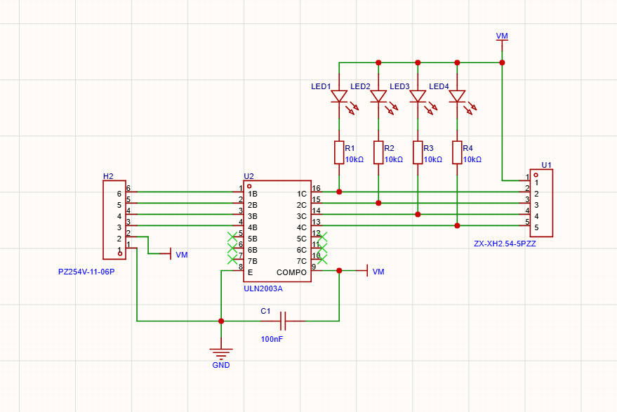
Four EEV channels through a ULN2003A穿过 ULN2003A 的四路 EEV 通道
The schematic routes four inputs through ULN2003A channels to the output connector and attaches an LED-resistor branch to each driven node.原理图让四路输入穿过 ULN2003A 通道到达输出连接器,并在每个驱动节点上接一支 LED 电阻支路。