
Arduino Breadboard Two-Digit Seven-Segment CounterArduino 面包板两位数码管计数器
For MEC104 Group A17, I handled most of the two-digit counter’s wiring, firmware, and debugging. Testing the display segments and measuring switch contacts resolved faults that code changes had not.我承担 MEC104 A17 组两位计数器的大部分搭建、编程与调试。数码管接法和六脚按键先后出问题,我通过逐段试灯、测量开关通断,把显示、暂停和复位调通。
- Timeline时间线
- 2024.04 - 2024.052024.04 - 2024.05
- Status状态
- Completed已完成
- Stack技术栈
- ArduinoEmbeddedSeven-Segment DisplayBCDBreadboardCourse Project
Two-Digit Counter两位计数器
Joining MEC104 Group A17 came just after my Arduino car project, making this my second encounter with embedded development. A counter sounded easier: increment a value at regular intervals and add pause and reset. I handled most of the technical implementation, including the breadboard, pin research, decoder wiring, Arduino program, button debugging, and integration. Other members took care of the report, video, and group administration.
加入 MEC104 A17 组时,我刚做过 Arduino 小车,这是第二次接触嵌入式。我以为计数器会轻松一些,写个程序,每隔一段时间加一,再给它接上暂停和复位就行。组内的面包板搭建、引脚查找、译码接线、Arduino 程序、按键调试和最终联调主要由我完成,其他组员负责报告、视频与小组事务。
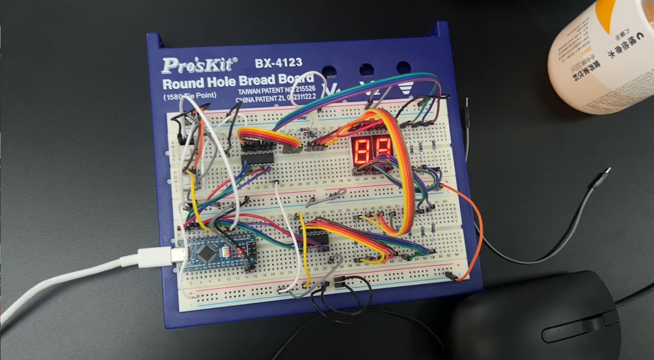
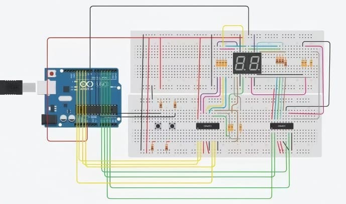
On the bench, an Arduino Nano sat beside two decoders, two displays, and a generous spread of jumper wires. The count had to be separated into tens and units, with each four-bit BCD value sent to an SN54LS47 driving its own digit. The report assigns the two BCD groups to D9 through D12 and D5 through D8. I wrote the digit-splitting and output code, then discovered how little a changing variable guaranteed about the physical display.
实物摆开以后,Arduino Nano 旁边是两颗译码器、两位数码管和一大片杜邦线。一个计数值要拆成十位与个位,各自通过四位 BCD 控制一颗 SN54LS47,再由它驱动对应数码管。报告把两组 BCD 输出分别画在 D9 到 D12、D5 到 D8。我写了拆位与输出程序,却很快发现,数字在程序里变化,显示未必会跟着正常变化。
Display Wiring数码管接线
Connecting the common pin to GND as shown in the course slides produced either darkness or scrambled digits. I checked my program and wiring first, and the TA could not explain the behavior either. Only after moving wires and testing individual segments at different levels did I establish that our hardware needed a common-anode connection, with the common pin at VCC. The slides used a common-cathode CD4511 simulation, so their device assumptions did not match the parts on our breadboard.
按课程 PPT 把公共端接到 GND,数码管有时全黑,有时乱码。我先查自己的程序和接线,TA 也没能解释清楚。后来在面包板上逐段换线、试高低电平,才发现手里的显示链路需要按共阳方式连接,公共端应接 VCC。PPT 用的是 CD4511 驱动共阴显示的仿真,实物器件的前提与它对不上。
After we reported the finding, the professor announced it to the class over the microphone. Other groups had been stuck at the same point. I could not yet explain the decoder output structure fully, but the physical tests were enough to correct the wiring. It was while organizing this portfolio that I revisited TI's LS47 documentation and connected its active-low, open-collector outputs with common-anode LEDs.
我们把发现告诉教授后,他用麦克风向全班说明了这件事,其他组也正卡在这里。那时我的知识还不足以完整解释译码器的输出结构,但实物测试已经足以让我修正接法。整理作品集时再查 TI 的 LS47 资料,才把低有效、开集电极输出与共阳 LED 的关系补齐。
Button Checks按键排查
The two six-pin latching switches took more work after the displays were running. We had no datasheet, and I did not know how to search for one by part number. Trying different connections produced missed presses, unstable readings, and sometimes two responses to one press. Editing the input conditions left the underlying hardware question open: which contacts actually connected in each switch position?
显示调通后,两个六脚自锁按键又让我折腾了一阵。没有数据手册,也不知道怎样按型号找资料,我先靠换线试,遇到过按下没反应、读数乱跳,以及按一次触发两次。继续改按键判断,仍然绕不开一个硬件问题,按下前后究竟哪几只脚导通。
I borrowed a multimeter from the instructor, checked continuity between pin pairs, and drew the internal connection map. I then connected pause and reset to D2 and D3, and both worked in the finished build.
我向老师借了万用表,用通断档逐对测引脚,把开关的内部连接关系画出来,再把暂停与复位接到 D2、D3。最终两个功能都能正常使用。
Demonstration and Archive演示与归档
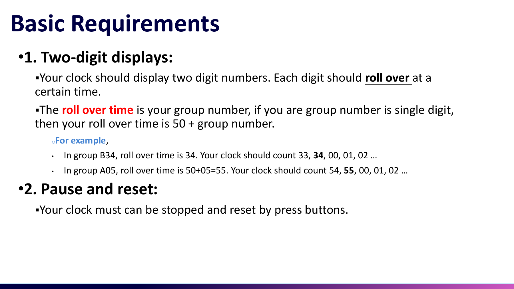
Assessment required two separately flashed versions. One returned to 00 after our group number, 17; the other rolled over after 99. I changed the threshold, flashed each version, and had the instructor check it. Both digits, pause, and reset worked during the classroom demonstration, and the TA awarded full marks.
考核要分别演示两个版本,一个计到组号 17 后回到 00,另一个计到 99 后回到 00。我修改阈值,分别烧录,再让老师逐项检查。课堂上,两位显示、暂停和复位都工作正常,TA 给了满分。
The firmware relied on polling and blocking delay() calls, and it looks distinctly like beginner work today. The debugging habit has lasted better. When a drawing disagrees with the hardware, I identify the actual parts and follow the current path; when a switch behaves strangely, I measure its contacts. Code still needs checking, but I stopped expecting code changes to repair every wiring problem.
当年的代码依赖轮询和阻塞式 delay(),今天看确实稚嫩。但这次实践留下的习惯很具体,图纸与实物不一致时,我会先确认器件和电流路径;按键状态不对,就先量导通关系。程序当然要检查,只是从那以后,我不再指望改代码能修好所有接线问题。
Development Notes开发笔记
Debugging records and technical notes tied to the decisions and artifacts on this project page.与这个项目页面中的设计决策和工程材料直接关联的调试记录与技术笔记。
Public Project Files公开项目资料
Uploaded evidence served from the public asset folder. Use the file index to preview documents, source code, media, PDFs, and downloadable artifacts without leaving the page.这里列出已经上传到公开目录的项目证据。可以在左侧索引里选择文件,在右侧直接预览文档、源码、媒体、PDF 和可下载附件。
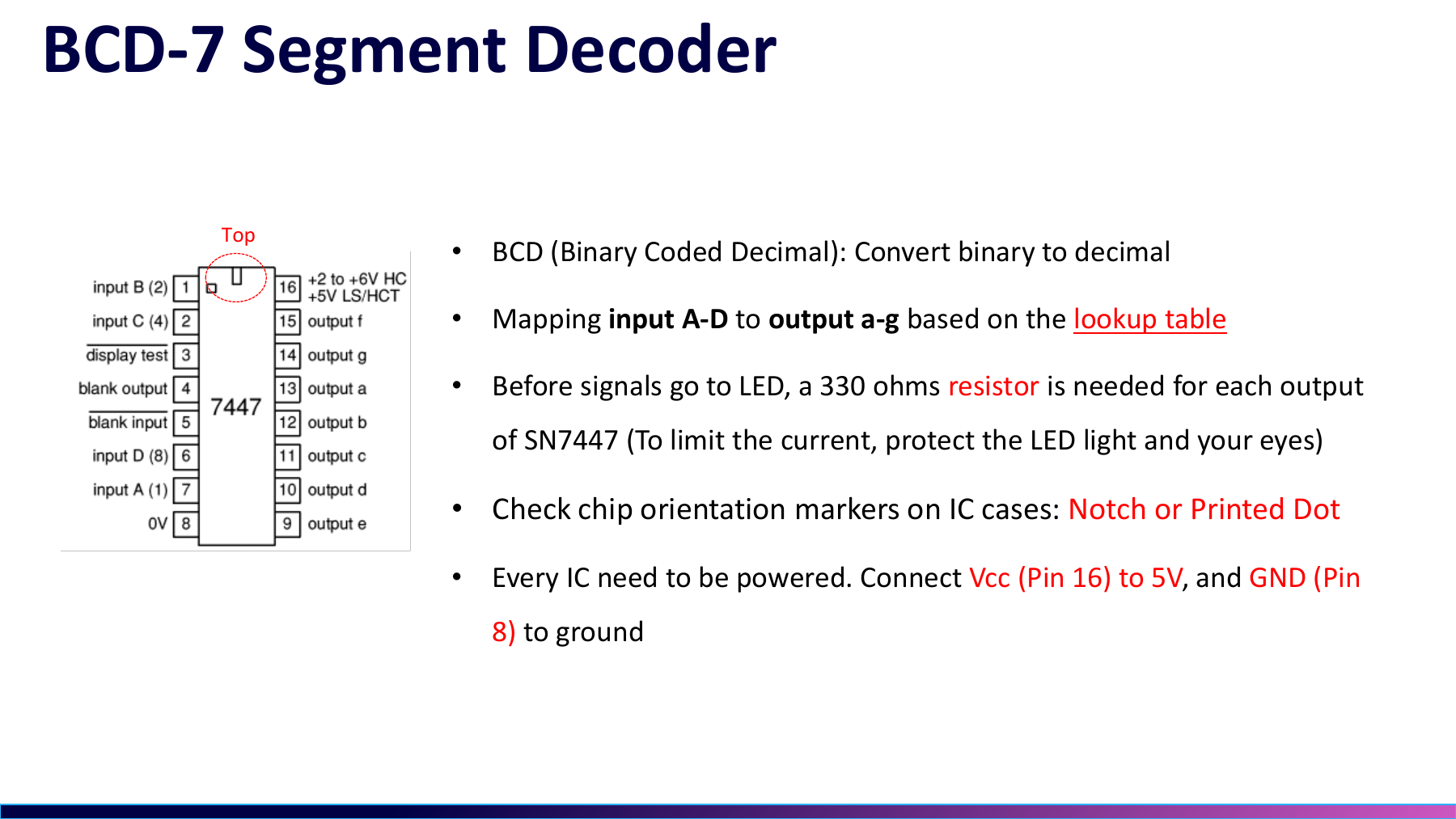
bcd-decoder-notes.png
PNG / 170.0 KB
Related Media相关媒体
Board photos, schematic sheets, videos, and test captures that show this project at specific stages.展示这个项目具体阶段的板卡照片、原理图分页、视频和测试截图。
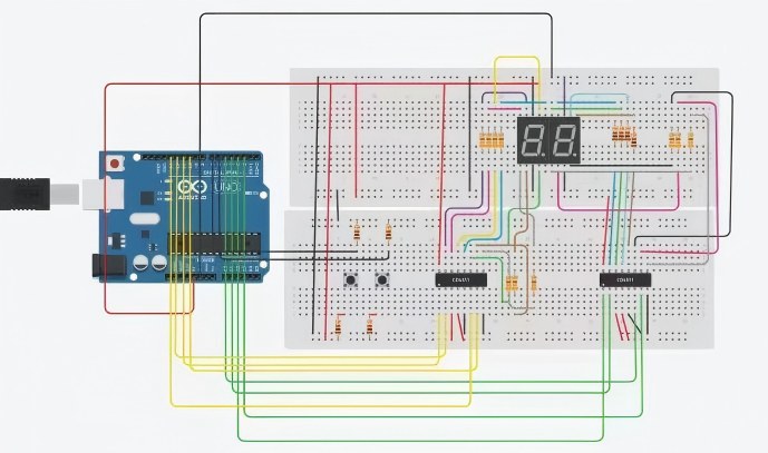
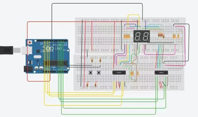
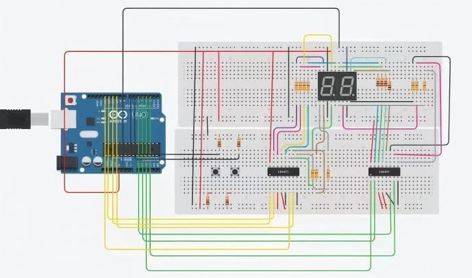
Two BCD display paths in the report两条 BCD 显示链的报告示意图
The report written by my teammates fans an Arduino Uno into two decoder/display branches and places two switches alongside them. It records the system topology; the breadboard I built and integrated used an Arduino Nano.组员撰写的作业报告从 Arduino Uno 分出两路译码/显示支路,并在旁边接入两个开关。它记录的是系统拓扑;我实际联调的面包板使用 Arduino Nano。
The 17-second clip only captured changing digits只留下数字变化的 17 秒现场视频
The clip only shows both digits changing while the Arduino Nano remains powered; it does not capture a button press. Pause and reset passed the classroom demonstration, but this video cannot serve as visual evidence for them.镜头只拍到了 Arduino Nano 上电后两位数字持续变化,没有拍下按键操作。暂停和复位最终通过了课堂演示,但不能拿这段视频充当它们的影像证据。
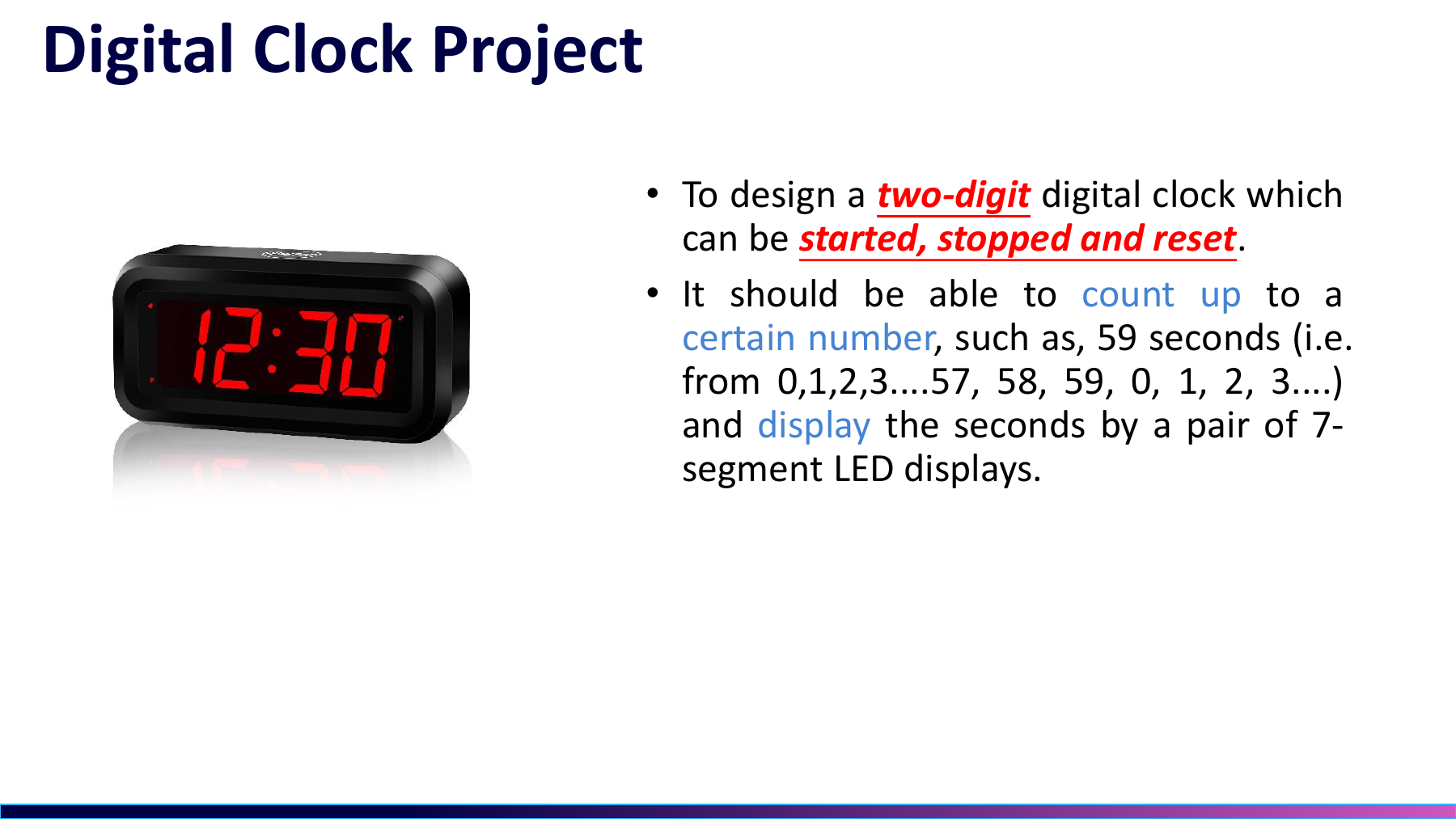
A17 rollover, pause, and reset requirementsA17 归零、暂停与复位要求
This slide defines the group-number build with two digits, rollover after 17, plus pause and reset. Counting through 99 was a separate version that I produced by changing the threshold, then flashed and demonstrated independently.这页课件定义了小组号版本,两位显示,到 17 后归零,并支持暂停和复位。计数到 99 再归零是另一个改完阈值后单独烧录、单独验证的版本。
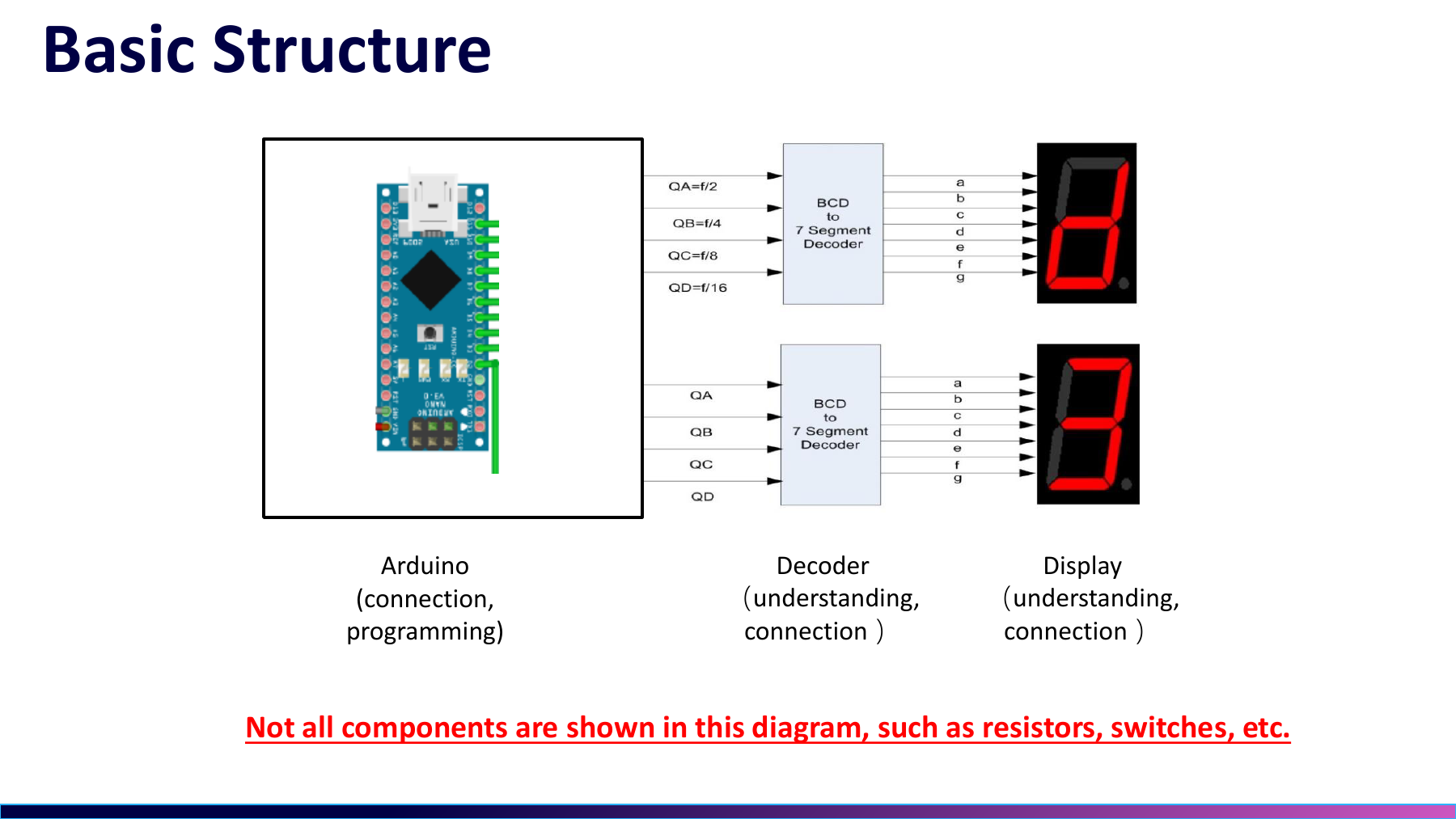
The three-stage display path I only understood later我后来才看懂的三段显示链路
The slide reduces the system to Arduino, BCD decoder, and seven-segment display. During the project I was connecting those stages one at a time; only later did I join software state, decoder outputs, and LED current into one explanation.课件把系统压成 Arduino、BCD 译码器和数码管三段。项目当时我只是在逐段接通;现在回看,才真正把软件状态、译码输出和 LED 电流路径连成一条链。
BCD logic does not define the current directionBCD 逻辑之外,还有电流方向
The slide marks A-D inputs, a-g outputs, power, and segment resistors around a 7447-style device. Four BCD bits select a number; whether it lights still depends on output polarity, the display common, and the actual current path.这页标出了 7447 类器件的 A-D 输入、a-g 输出、供电和段限流。四位 BCD 只决定数字;显示能否点亮,还取决于驱动极性、公共端和实际电流路径。
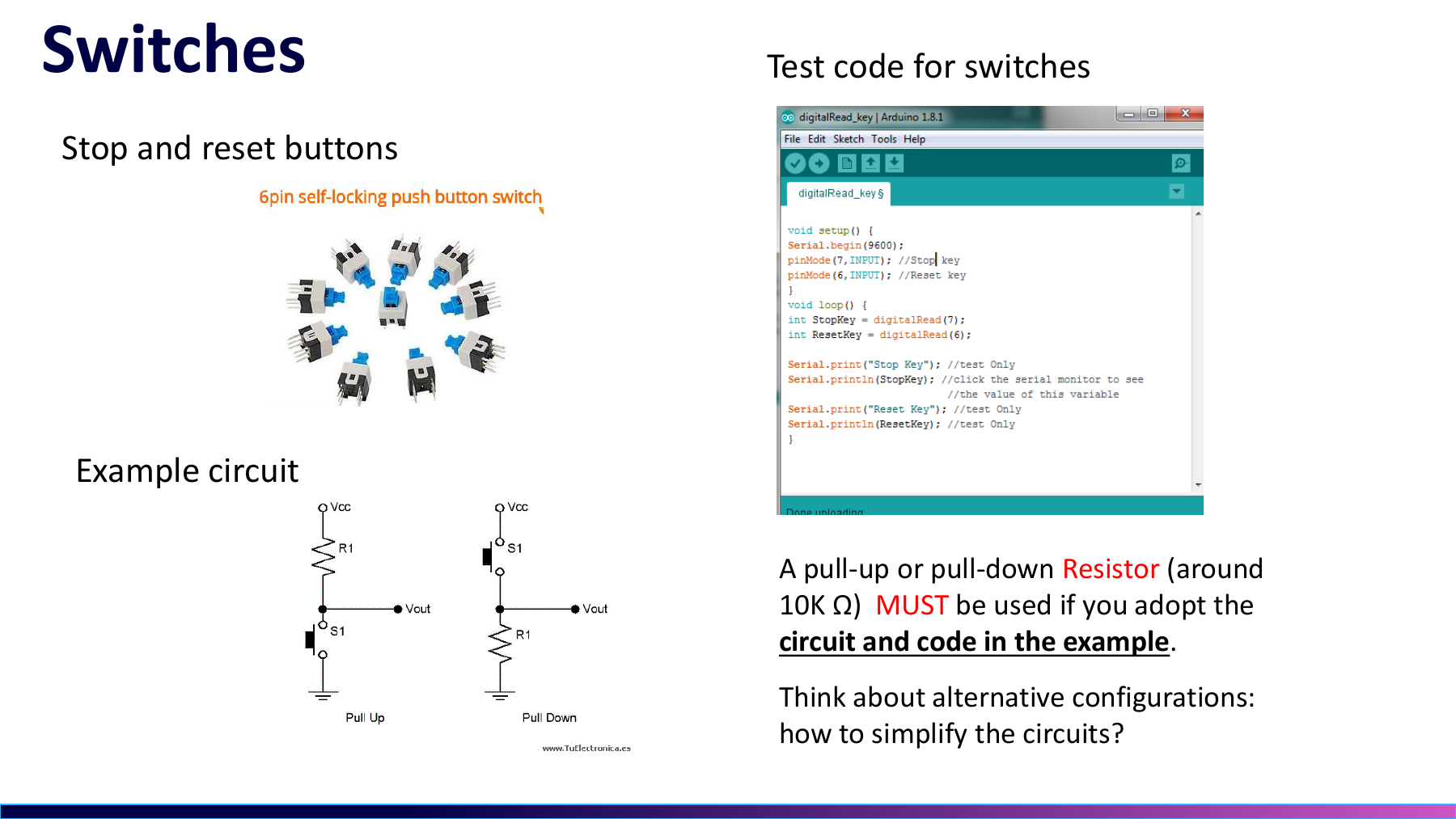
A six-pin switch mapped with a multimeter靠万用表摸清的六脚按键
Without a matching datasheet, the six pins produced no response, unstable readings, and repeated triggers. I borrowed a multimeter and checked continuity pair by pair before reconnecting the pause and reset functions.没有对应数据手册时,六只脚让我遇到没反应、乱跳和重复触发。我借来万用表逐对测通断,先确认按下前后的内部连接,再把暂停和复位接回程序。
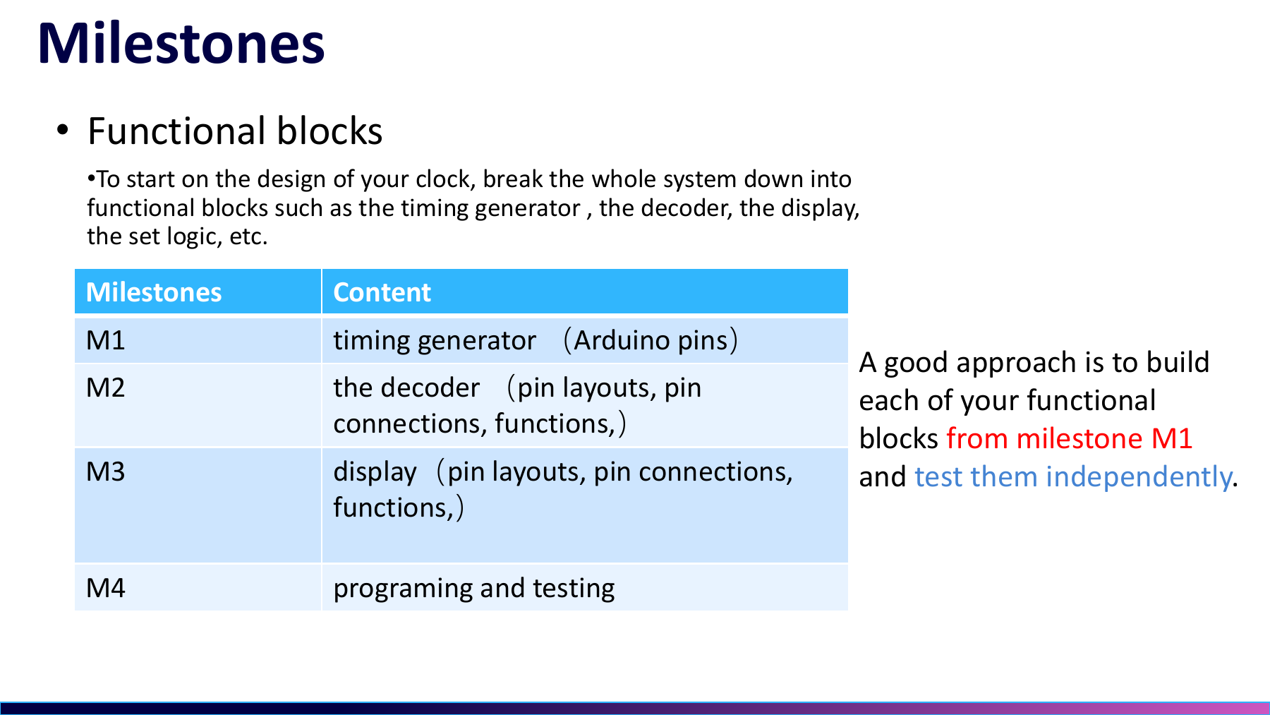
From a one-digit demo to two-digit integration从一位 demo 到两位联调
Development roughly followed the course sequence. I read the material, ran a one-digit BCD example, wired two digits, split units and tens, added the buttons, then integrated the system. The two demo sketches were early checkpoints, not the final program.实际开发大致沿着课件顺序推进。我先读资料和跑一位 BCD 示例,再铺两位接线、拆分个位与十位、加入按键,最后联调。两份 demo sketch 都只是前期检查点。
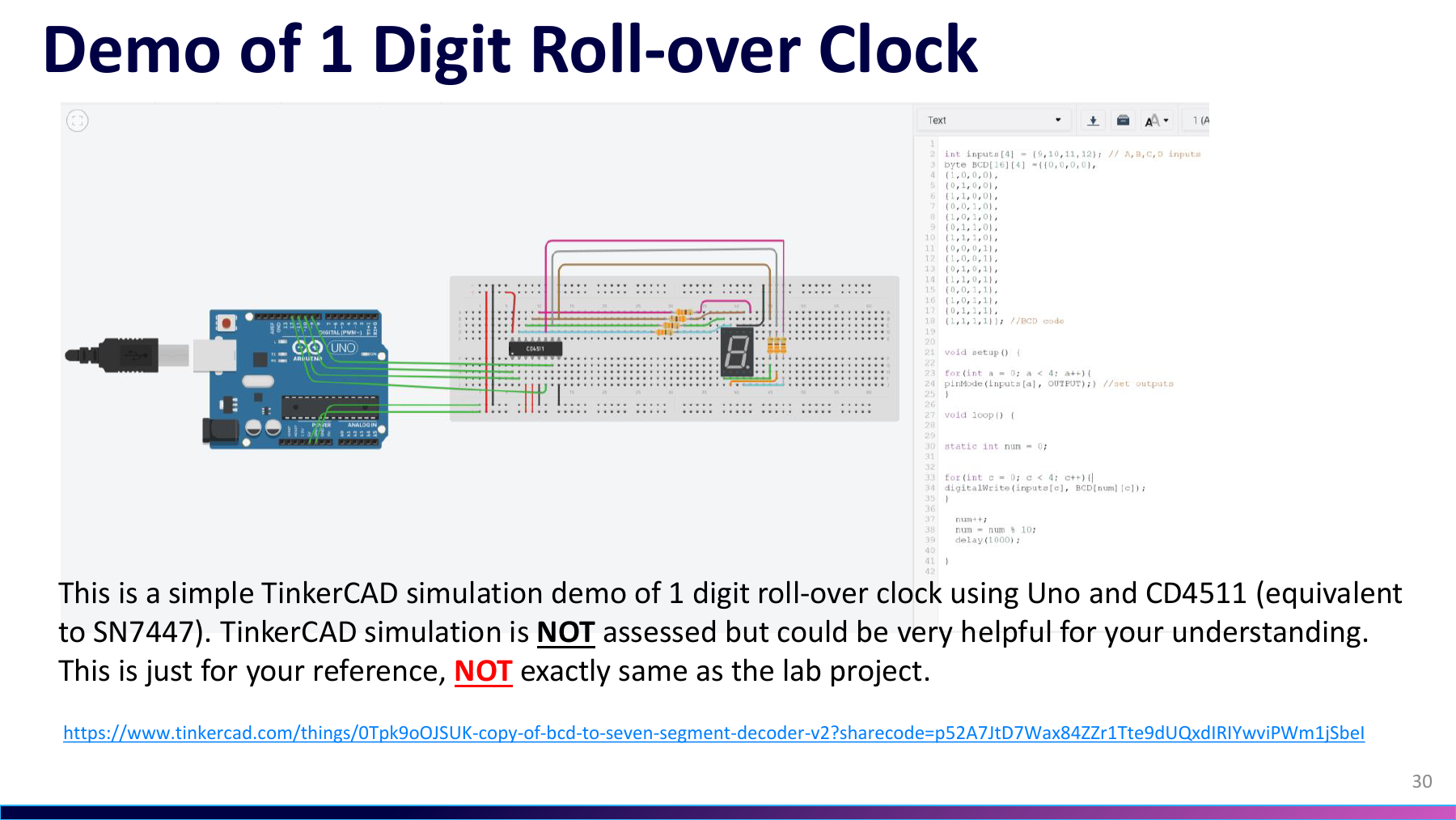
The CD4511 simulation omitted a polarity assumption漏掉极性前提的 CD4511 仿真
TinkerCAD uses a CD4511 to drive a common-cathode display, while the physical LS47 path was intended for common-anode operation. Both decode BCD, but they cannot use the same common-pin connection; that mismatch produced the dark or scrambled display.TinkerCAD 用 CD4511 驱动共阴数码管,实物的 LS47 路径却面向共阳显示。两者都做 BCD 译码,但不能共用同一个公共端接法;这正是当时不亮/乱码故障的来源。
Two decoder branches in the A17 reportA17 报告中的双译码支路
The cropped report places two decoders between an Arduino Uno and two displays, with resistors and switches nearby. It captures the intended branch relationship; the circuit I built and integrated on the bench used an Arduino Nano.报告裁图把两颗译码器放在 Arduino Uno 与两位数码管之间,旁边还有电阻和开关。它说明了预期支路关系;我实际搭建和联调的是 Nano 面包板版本。
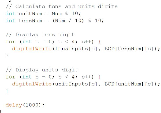
How one state becomes units and tens一个状态怎样拆成个位和十位
`Num % 10` extracts units and `(Num / 10) % 10` extracts tens. Each result selects a four-bit BCD row for its own decoder; this was the two-digit split I learned while building the project.`Num % 10` 取个位,`(Num / 10) % 10` 取十位;两个结果各自查一行四位 BCD,再送进两颗译码器。这是我当时边查资料边学会的两位显示拆分。
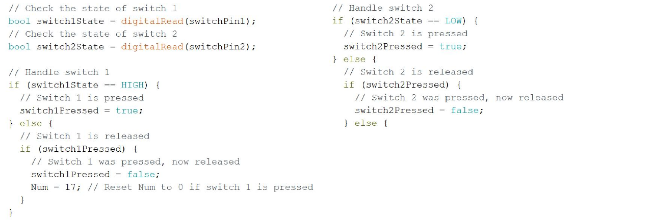
A button screenshot that cannot settle the final wiring无法替最终硬件下结论的按键截图
The excerpt checks switch 1 with HIGH and switch 2 with LOW, while the report also mentions a pull-up. Both buttons passed the classroom demonstration, but without the final wiring and source this image cannot prove a tidy polarity or debounce implementation.截图里 switch 1 用 HIGH,switch 2 用 LOW,报告文字还提到上拉。最终两个按键确实通过了课堂演示,但缺少最终源码与接线,不能据此补出一套整齐的极性或消抖实现。