

DIY Laptop CoolerDIY 压风式笔记本散热器
I built an acrylic-and-foam laptop cooler, with a Windows application sending temperatures over Bluetooth to an ESP32 fan controller. A later STM32 board reached serial control but never rejoined the complete system.我做了一台亚克力与泡棉散热器,用 Windows 程序读取温度,经蓝牙控制 ESP32 和风扇。后来重画的 STM32 板完成了串口控制,尚未重新接成完整的温控整机。
- Timeline时间线
- 2024.08 - 2024.092024.08 - 2024.09
- Status状态
- Archived Prototype原型归档
- Stack技术栈
- ESP32STM32PCBPWMBluetoothCoolingDesktop ToolCAD
Airflow and Temperature风道与温度
This cooler began with my laptop overheating and dropping frames in CSGO. I had already adjusted the machine and cleaned its cooling system. Looking at an ordinary cooling pad, I could see plenty of air moving without knowing how much entered the laptop's bottom intake. I wanted to seal the surrounding gaps and make the fan respond to the computer's temperature.
做这个散热器的起因很直接,玩 CSGO 时,笔记本高温掉帧。我已经调过机器、清过灰,再看普通散热底座,总觉得风扇吹得很热闹,进到笔记本底部风口的气流却未必有多少。我想试着把四周封起来,让风少绕一些路,同时让风扇跟着电脑温度调整。
I built an acrylic base with foam against the laptop underside to reduce air escaping around it. For temperature, I chose the readings already available inside the computer. An external probe would add cost and measure farther from the CPU and GPU. Using the internal readings meant finding a way to bring them onto my own controller board.
结构上,我做了亚克力底座,用泡棉贴合笔记本底部,减少气流从四周逃走。温度则直接从电脑内部读取,不再加外置探头。外壳附近的温度与 CPU、GPU 的状态隔着一段距离,还要增加器件成本;既然电脑已经能提供内部读数,我就想把它接到自己的控制板上。
My First Desktop Controller第一套上位机
I had no WinForms or desktop-control experience. With CSDN material and AI assistance, I assembled a C# application targeting .NET Framework 4.7.2. The application source uses LibreHardwareMonitor for temperature monitoring, then provides COM-port scanning, connection, display, and automatic transmission. Lines such as CPU62.7 and GPU71.3 leave through a 115200-baud virtual serial port and reach an ESP32 using BluetoothSerial.
此前我没学过 WinForms,也没有写上位机的经验。我边查 CSDN 边借助 AI,做出一个面向 .NET Framework 4.7.2 的 C# 程序。上位机源码调用 LibreHardwareMonitor 读取温度,提供 COM 口扫描、连接、显示和自动发送,再把 CPU62.7、GPU71.3 这样的报文经 115200 波特率的虚拟串口送出去。接收端是使用 BluetoothSerial 的 ESP32。
I did not want using a cooling stand to involve opening VS Code, attaching a USB-UART adapter, and typing commands. A cooler should not come with that much homework. My original plan put every control in the GUI, but I finished only connection and temperature transmission there. Five physical buttons handled mode, PWM frequency, and manual duty. The incomplete GUI plan had one useful consequence: the fan could be adjusted directly after power-on.
我不想让一个散热底座的使用过程变成打开 VS Code、接 USB-UART、手敲命令。散热器还附送一份操作作业,实在没必要。原本我想把所有操作都放进 GUI,最后只完成了连接与温度发送,模式、PWM 频率和手动占空比交给五个实体按键。这个没做完整的界面方案倒也有实用之处,通电以后,伸手就能调风扇。
The first successful Connect click was exciting. Windows found ESP32_Bluetooth, temperatures appeared in the window, and the fan on the desk changed speed. A program on my computer was controlling a board I had soldered. The 3 min 57 s demonstration preserves the operation across Windows, Bluetooth, OLED, buttons, and the physical fan.
第一次在 Windows 点下 Connect,找到 ESP32_Bluetooth,看着温度出现在窗口里,随后桌上的风扇真的变速了,我很兴奋。写在电脑里的程序终于控制到了自己焊的板子。3 分 57 秒的演示保留了 Windows、蓝牙、OLED、按键和风扇之间的完整操作。
Temperature and Fan Control温度与风扇控制
The ESP32 firmware generates PWM on GPIO 5, initially at 15 kHz with 8-bit resolution. Automatic modes use simple proportional temperature mapping, alongside manual duty control. I spent roughly half a week trying PID, without completing an implementation. In retrospect, I had reached for tuning before defining a target temperature, selecting the exact sensor, or recording the thermal response.
ESP32 固件用 GPIO 5 输出 PWM,初始频率是 15 kHz,分辨率为 8 位。自动模式采用温度的简单比例映射,另有手动占空比设置。我也花过大约半周尝试 PID,最终没有实现。那时连目标温度、传感器选择和热响应记录都没定义清楚,现在回看,急着调 PID 确实太早。
I also reconsidered the OLED label Fan Speed. Its variable was duty cycle; the program never measured RPM. A fan manufacturer's PWM and speed-monitoring guide makes the distinction between the command input and tach feedback explicit.
OLED 上的 Fan Speed 也是我后来才意识到的问题,显示变量实际是占空比,程序没有测 RPM。风扇厂商的 PWM 与转速监测说明把控制输入与 tach 反馈明确分开。
The application attempts one temperature transmission every five seconds, alternating CPU and GPU; the firmware updates its output from the higher peak in a 30-second window.
上位机每五秒尝试发送一条,CPU、GPU 交替,固件再用 30 秒窗口中的较高峰值更新输出。
Two Hardware Versions两版硬件
For the ESP32 version, I completed the schematic, EasyEDA project, and Gerber files, then had the board fabricated, soldered it, powered it, and installed it in the acrylic base. It carried two fan interfaces, power conversion, an OLED, and five buttons. There was no separate fan-driver IC; PWM went to the fan's own control interface. This version completed the computer-temperature-to-fan integration, and I used it for about two or three days.
我为 ESP32 版完成了原理图、EasyEDA 工程与 Gerber,随后制造、焊接、上电并装入亚克力底座。板上有两路风扇接口、电源变换、OLED 和五个按键,没有另加风扇驱动芯片,PWM 接到风扇自身的控制接口。这一版完成了从电脑温度到实体风扇的整机联调,我实际用了大约两三天。
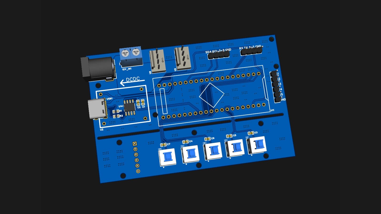
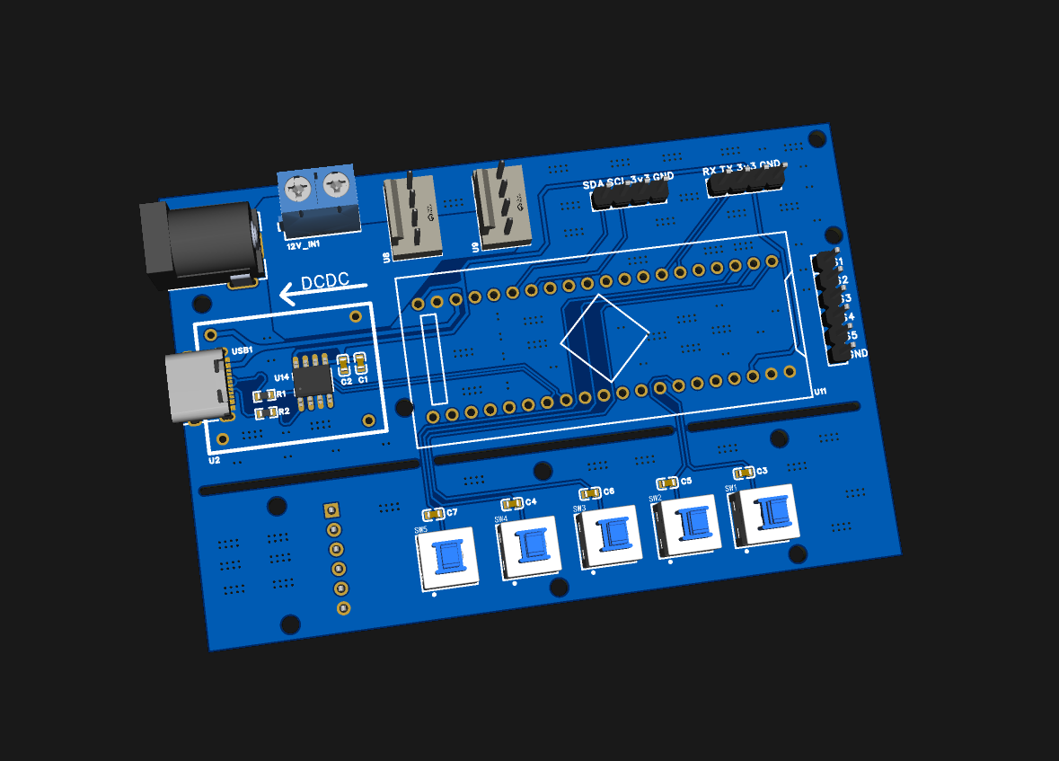
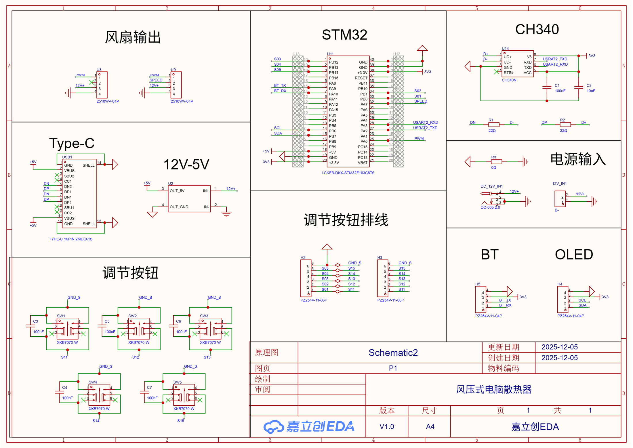
I later redrew the controller around an STM32F103C8T6, reorganizing and widening some traces, changing placement, reducing board size, and adding a CH340N USB-UART interface. I soldered and powered this board too, and wrote its firmware. Serial commands from VS Code produced replies and changed the fan speed. I stopped this version at serial control, with the external Bluetooth link still awaiting reconnection to the Windows temperature application.
后来我用 STM32F103C8T6 重画控制板,重新整理并加宽部分走线,调整元件布局、缩小板子,再加入 CH340N USB-UART。我也把这块板焊好、上电,并写了固件。从 VS Code 经串口发命令,它能够回复命令,让风扇变速。这一版做到串口控制就停了,外接蓝牙还没连回 Windows 温度程序。
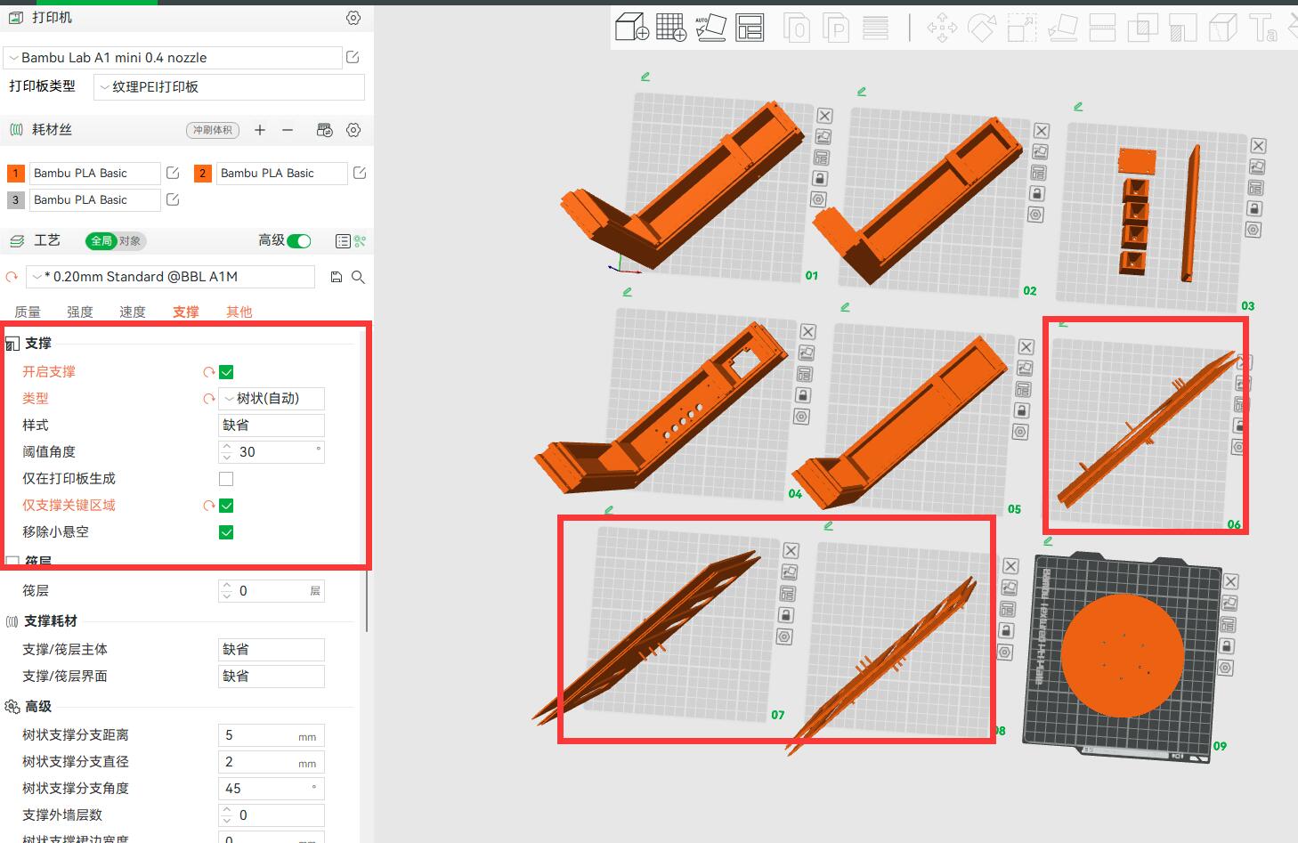
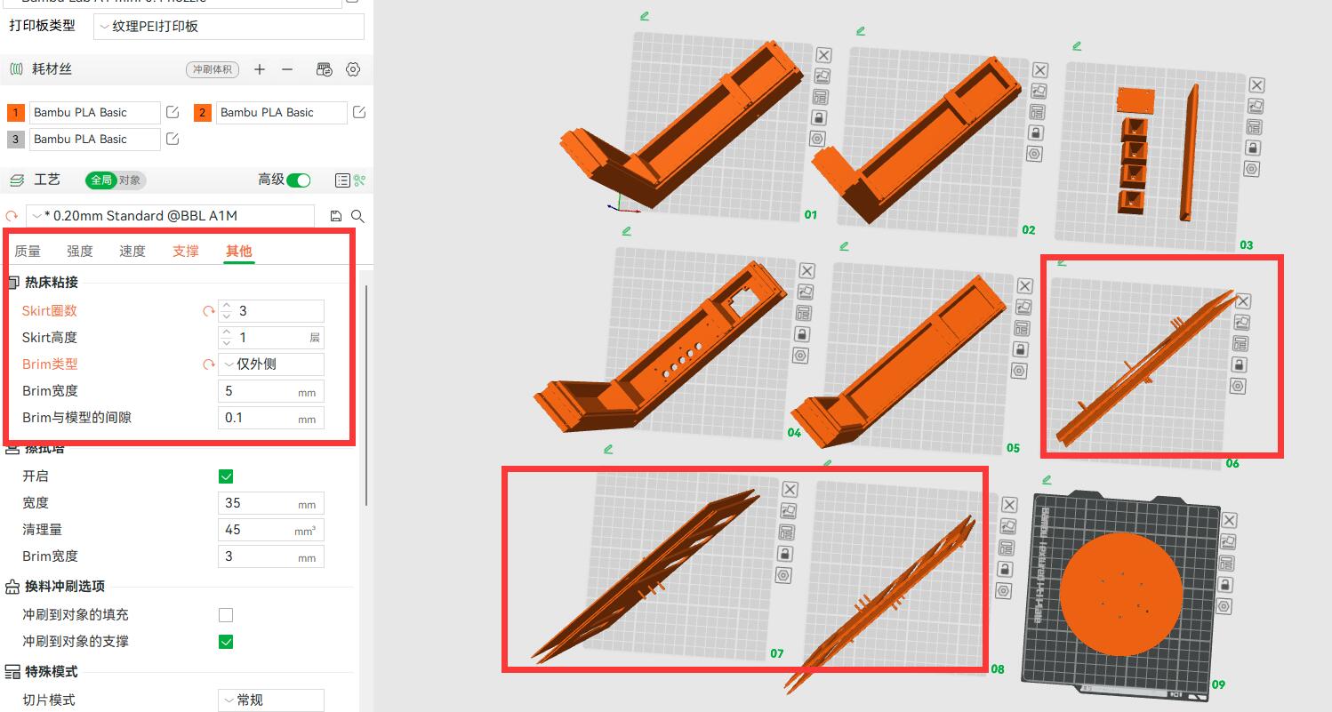
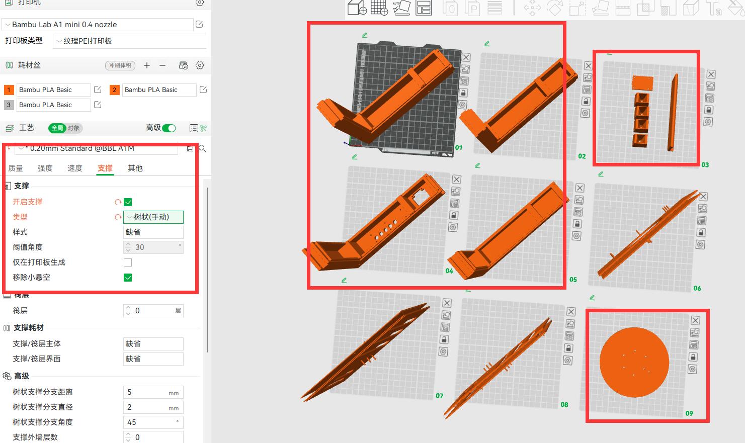
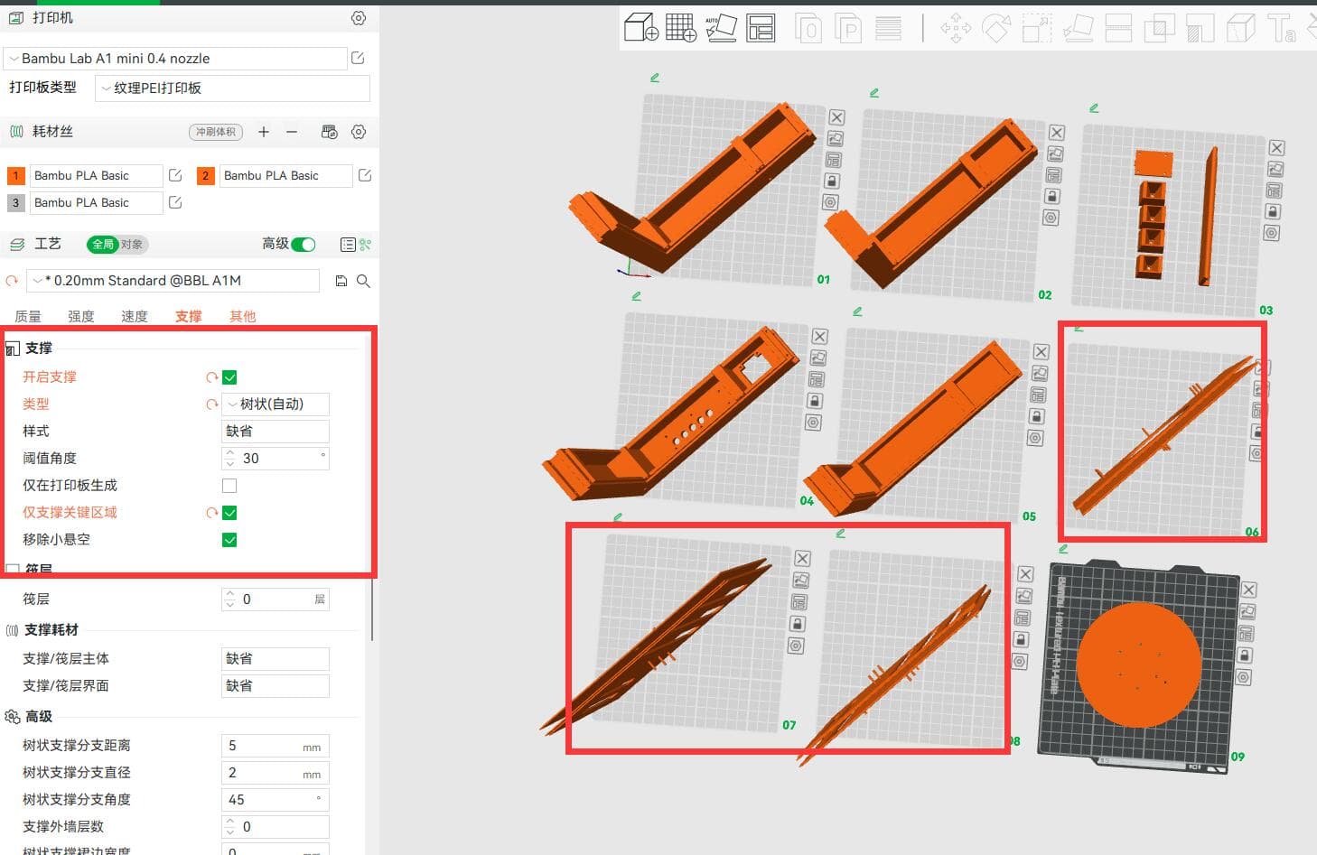
I explored another enclosure for the Bambu Lab A1 mini, modeling and splitting the body across nine build plates in the 3MF project. I compared automatic and manual tree supports, orientation, brim, and skirt settings. That route stopped at slicing previews.
外壳也试过另一条路线。我为 Bambu Lab A1 mini 建模、拆件,在 3MF 中排成九块切片板,比较过自动与手动树状支撑、零件朝向、Brim 和 Skirt。做到切片预览就停了。
Using the Prototype实际使用
During those two or three days, I felt that cooling improved. I remember roughly 20 to 30 additional FPS in CSGO and a maximum temperature falling from about 92 to 93°C to around 84°C.
使用那两三天,我觉得散热有改善。按现在记得的量级,CSGO 大约增加了 20 到 30 FPS,最高温度从约 92 到 93°C 降到约 84°C。
The cooler I built could go under my own laptop and adjust its fan to the computer's temperature, just as I had first wanted. I was thrilled the first time I clicked Connect and watched the fan on my desk change speed with those readings.
我把最初那个让风扇跟着电脑温度调整的想法,做成了能放到自己电脑下面使用的散热器。第一次点下 Connect,看着桌上的风扇跟着电脑里的温度读数变速,我特别兴奋。
Development Notes开发笔记
Debugging records and technical notes tied to the decisions and artifacts on this project page.与这个项目页面中的设计决策和工程材料直接关联的调试记录与技术笔记。
Public Project Files公开项目资料
Uploaded evidence served from the public asset folder. Use the file index to preview documents, source code, media, PDFs, and downloadable artifacts without leaving the page.这里列出已经上传到公开目录的项目证据。可以在左侧索引里选择文件,在右侧直接预览文档、源码、媒体、PDF 和可下载附件。
diy-cooling-3d-print-preview-3.jpg
JPEG / 143.5 KB
Related Media相关媒体
Board photos, schematic sheets, videos, and test captures that show this project at specific stages.展示这个项目具体阶段的板卡照片、原理图分页、视频和测试截图。
One Click Connected Windows Temperature to Fan Duty一次点击,把 Windows 温度接到风扇占空比
The 3 min 57 s recording demonstrates the integrated Windows, Bluetooth SPP, and ESP32 chain. Temperatures appear in the app, duty and mode appear on the OLED, and the fan responds to data and buttons. The recording does not contain synchronized temperature, RPM, or performance logs.这段 3 分 57 秒录像演示了 Windows、Bluetooth SPP 与 ESP32 完整链路。上位机显示温度,OLED 显示占空比与模式,风扇响应数据和按键;录像不包含同步温度、RPM 或性能日志。
Nine A1 mini Build Plates That Remained Digital停留在数字阶段的九块 A1 mini 切片板
The long enclosure was split across nine A1 mini build plates with automatic tree supports. Modeling and slicing were completed; printing and assembly were not.长外壳被拆分到九块 A1 mini 切片板,并配置自动树状支撑;建模与切片完成,打印和装配没有进行。
Brim and Skirt Settings That Never Reached the Printer没有走到打印的 Brim 与 Skirt 设置
The unprinted enclosure used three skirt loops, a 5 mm outer brim, and a 0.1 mm gap in this slicing pass. These settings record preparation, not a fabricated result.这次切片为未打印外壳设置了三圈 Skirt、5 mm 外侧 Brim 与 0.1 mm 间隙;这些参数只记录准备过程,不代表制造结果。
Reorienting the Enclosure Parts With Manual Tree Supports手动支撑下重新摆放外壳分件
A manual-tree-support pass compares orientations for the same enclosure parts. This mechanical revision remained a model and slicing study.手动树状支撑方案比较了同一组外壳分件的摆放姿态;这版机械结构停留在模型与切片研究阶段。
A Tighter STM32 Board Without the Complete Wireless Chain更紧凑、但未接回完整无线链路的 STM32 板
The STM32 revision reorganized routing and reduced board size while retaining 12 V input, USB-C, two fan interfaces, OLED/Bluetooth headers, and five buttons. The PCB was soldered, powered, and tested by serial fan commands, but not installed in the cooler.STM32 版本重新整理走线并缩小板卡,同时保留 12 V 输入、USB-C、两路风扇、OLED / Bluetooth 排针和五个按键;PCB 完成焊接、上电与串口风扇命令测试,但没有装入散热器。
USB-UART and Dual-Fan Interfaces on the STM32 VersionSTM32 版的 USB-UART 与双风扇接口
The schematic combines an STM32F103C8T6, CH340N USB-UART, dual fan interfaces, 12 V-to-5 V conversion, five buttons, and OLED/Bluetooth headers. Serial fan control was tested; the Windows automatic-temperature path was not restored.原理图组合了 STM32F103C8T6、CH340N USB-UART、双风扇接口、12 V 转 5 V、五个按键及 OLED / Bluetooth 排针;串口风扇控制完成测试,Windows 自动温度链路没有恢复。