Note 01 of 04: 笔记 01 / 04:Capacitor Parasitics and Self-Resonance电容的寄生参数与自谐振
The 0603 capacitors on the AD831 mixer board worked through as C plus ESL plus ESR: where each one self-resonates, what it looks like at 10.7 MHz and 120 MHz, why the signal path asks for C0G, and why a through-hole electrolytic stops helping long before RF.把 AD831 混频器板上的几颗 0603 电容按电容、ESL、ESR 串联的模型算一遍:各自在哪里自谐振,10.7 MHz 和 120 MHz 下是什么样子,信号路径为什么要求 C0G,插件电解电容为什么远没到射频就帮不上忙。
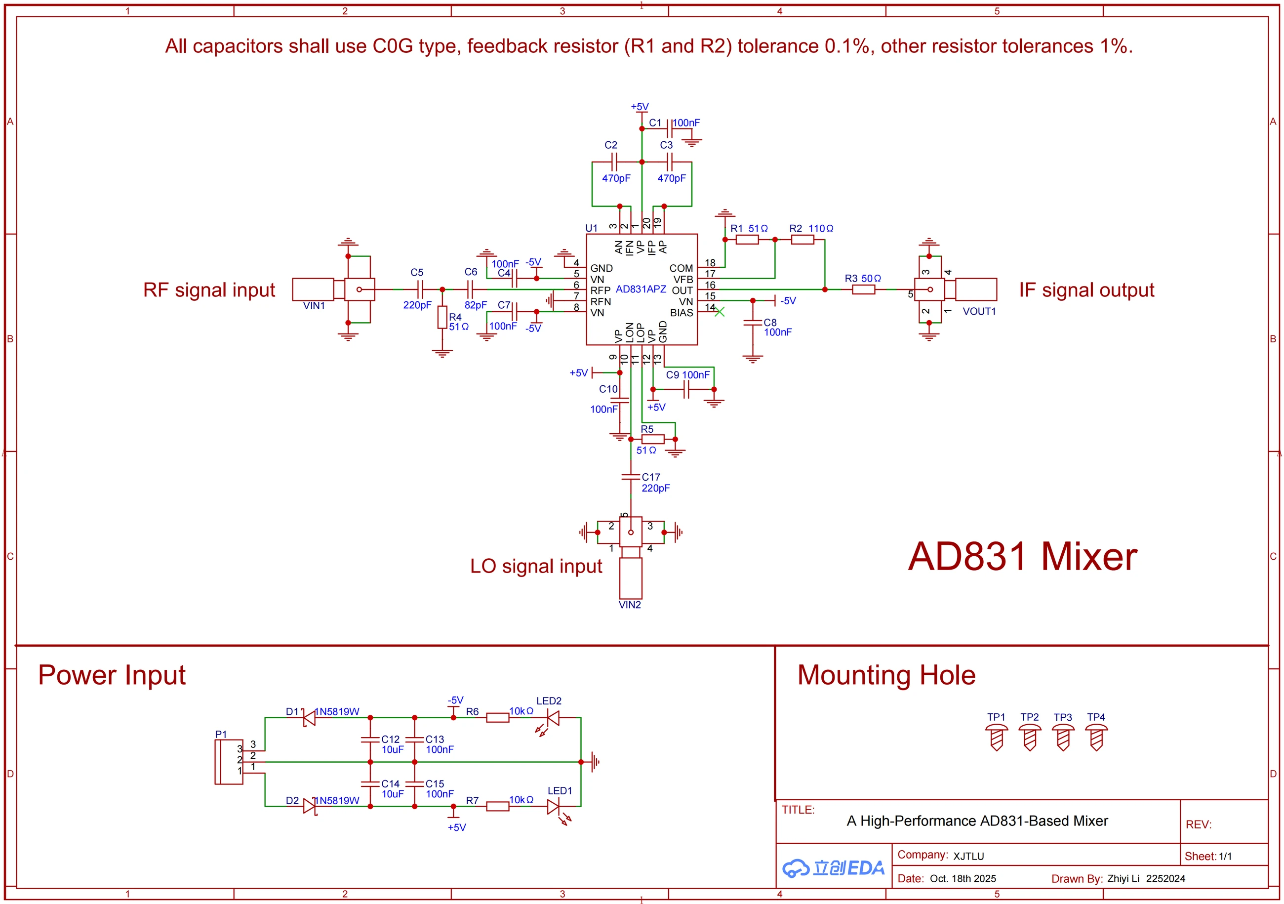
Across the top of the final schematic runs a line of red text: All capacitors shall use C0G type. The input coupling capacitors went from 10 nF in V1 to 220 pF and 82 pF, and the IF filter capacitors are 470 pF. The lectures had made the point that at high frequency a capacitor is more than a capacitor; it also carries ESR and ESL in series. What each of these parts turns into at 120 MHz is worth working out one at a time.
最终版原理图顶上有一行红字:All capacitors shall use C0G type。输入耦合电容从 V1 的 10 nF 换成了 220 pF 和 82 pF,中频滤波电容用的是 470 pF。课上讲过,电容在高频下不只是一个电容,它身上还串着 ESR 和 ESL。这几颗电容到了 120 MHz 各自是什么样子,值得一颗一颗算出来。
Capacitor Equivalent Circuit电容的等效电路
A surface-mount capacitor can be modelled as capacitance C in series with an equivalent series inductance, ESL, and an equivalent series resistance, ESR. At low frequency the capacitive reactance dominates and the impedance falls as frequency rises. At one frequency the capacitive and inductive reactances cancel, the impedance bottoms out at the ESR, and that point is the self-resonant frequency, f = 1 / (2π √(L·C)). Above it the inductance dominates and the part behaves like an inductor in the circuit. The impedance curve therefore takes a V shape (Murata explains the curve here). Smaller packages have less ESL, and larger capacitance pulls the self-resonance lower.
一颗贴片电容可以看成电容 C、等效串联电感 ESL 和等效串联电阻 ESR 串在一起。低频时容抗占主导,阻抗随频率升高而下降;频率升到某一点,容抗和 ESL 的感抗正好抵消,阻抗降到最低,只剩 ESR,这个频率叫自谐振频率,f = 1 / (2π √(L·C));再往上,感抗占主导,这颗电容在电路里已经表现得像一个电感了。阻抗曲线于是呈一个 V 字形(村田对这条曲线的讲解)。封装越小,ESL 越小;容量越大,自谐振频率越低。
0603 Capacitors at 120 MHz0603 电容在 120 MHz 下的阻抗
All the capacitors on the board are 0603. Taking 0.7 nH as the ESL, their self-resonant frequencies and reactances work out as follows:
板上的电容都是 0603 封装。ESL 按 0.7 nH 估,几颗电容的自谐振频率和电抗如下:
| Capacitor | Self-resonance | Reactance at 120 MHz | Reactance at 10.7 MHz |
|---|---|---|---|
| 10 nF | about 60 MHz | +0.4 Ω (inductive) | −1.4 Ω |
| 470 pF | about 278 MHz | −2.3 Ω | −31.6 Ω |
| 220 pF | about 406 MHz | −5.5 Ω | −67.6 Ω |
| 82 pF | about 664 MHz | −15.7 Ω | −181 Ω |
| 电容 | 自谐振频率 | 120 MHz 下的电抗 | 10.7 MHz 下的电抗 |
|---|---|---|---|
| 10 nF | 约 60 MHz | +0.4 Ω(感性) | −1.4 Ω |
| 470 pF | 约 278 MHz | −2.3 Ω | −31.6 Ω |
| 220 pF | 约 406 MHz | −5.5 Ω | −67.6 Ω |
| 82 pF | 约 664 MHz | −15.7 Ω | −181 Ω |
The 10 nF self-resonates around 60 MHz, so by 120 MHz it is past resonance and shows a small inductive reactance under half an ohm. As a coupling capacitor it still passes the signal, because capacitive or inductive, its impedance is negligible. It has stopped being a capacitor, though, and using it to set a high-pass corner is out of the question. The 220 pF and 82 pF both self-resonate at several hundred megahertz and are still well-behaved capacitors at 120 MHz, which is why the 14.5 MHz and 38 MHz corners calculated with ideal capacitors hold up.
10 nF 的自谐振频率在 60 MHz 左右,到 120 MHz 已经过了谐振点,表现为不到半欧的小感抗。当耦合电容用,它照样能把信号放过去,因为不管容性还是感性,阻抗都小到可以忽略;可它已经不是电容了,用它来定一个高通转折频率无从谈起。220 pF 和 82 pF 的自谐振频率都在几百兆赫,120 MHz 下还是规规矩矩的电容,按理想电容算出来的 14.5 MHz、38 MHz 两个转折点才站得住。
The two 470 pF parts hang on the IF current outputs and form a low-pass with the chip's roughly 14 Ω internal load. At 10.7 MHz their reactance is 31.6 Ω, far above 14 Ω, so the IF passes almost untouched. Their self-resonance sits around 278 MHz, which puts the 250.7 MHz sum product close to resonance, where the impedance is down to the ESR and the shunt to ground is even stronger. For a filter capacitor, that is a happy accident.
470 pF 那两颗挂在中频电流输出脚上,和芯片内部约 14 Ω 的负载组成低通。10.7 MHz 下它的容抗是 31.6 Ω,比 14 Ω 大得多,中频基本不受影响;它的自谐振频率在 278 MHz 左右,250.7 MHz 的和频差不多落在谐振点附近,那里阻抗只剩 ESR,对地分流得反而更狠。对一颗滤波电容来说,这算是歪打正着。
C0G and X7RC0G 与 X7R
The red line asks for C0G because of the dielectric. C0G is a class 1 ceramic: its capacitance barely moves with temperature or DC bias, and it doesn't age. Class 2 dielectrics such as X7R and X5R use barium titanate, which gives high permittivity and small parts, but their capacitance falls noticeably with DC bias and over time (Murata's dielectric classification, Kyocera AVX on DC bias). Capacitors in the signal path set corner frequencies with their value, so if the value drifts, the corner moves with it. In the final BOM the 470 pF, 220 pF and 82 pF parts are all NP0/C0G. The 100 nF supply capacitors are X7R and the 10 µF is X5R; decoupling only needs low impedance, so some capacitance loss there does no harm.
那行红字要求用 C0G,是因为介质。C0G 属于一类陶瓷介质,容量几乎不随温度、直流偏压变化,也没有老化;X7R、X5R 这些二类介质用的是钛酸钡,介电常数高、体积小,但容量会随直流偏压和时间明显下降(村田的介质分类说明,Kyocera AVX 对直流偏压的讲解)。信号路径上的电容要靠容量去定转折频率,容量一漂,转折点就跟着跑。最终 BOM 里,470 pF、220 pF、82 pF 都选的是 NP0/C0G;电源上的 100 nF 是 X7R,10 µF 是 X5R,去耦只要求低阻抗,容量差一些没关系。
Decoupling and Electrolytic Capacitors去耦电容与电解电容
A 10 µF and a 100 nF sit in parallel next to the power connector. With the same 0.7 nH, the 10 µF self-resonates near 1.9 MHz and the 100 nF near 19 MHz. The slides split the work as 10 µF for ripple from 10 kHz to 5 MHz and 100 nF for noise from 1 MHz to 100 MHz, which lands each range in the low-impedance region of its own capacitor. Pairing a large and a small value is how the whole span gets covered.
电源接口边上并着一颗 10 µF 和一颗 100 nF。按同样的 0.7 nH 算,10 µF 的自谐振频率约 1.9 MHz,100 nF 约 19 MHz。PPT 里写的分工是 10 µF 管 10 kHz 到 5 MHz 的纹波、100 nF 管 1 MHz 到 100 MHz 的噪声,正好落在两颗电容各自的低阻抗区间里,一大一小两颗搭着用,就是为了把这一段频率都盖住。
A through-hole aluminium electrolytic loses badly on this chart. The electrolyte's high resistivity makes for a large ESR, and the leads and wound construction add more ESL. Even at the same 10 µF, once the frequency passes a kilohertz the electrolytic's impedance climbs well above that of a surface-mount ceramic (Murata's comparison). A through-hole electrolytic on a breadboard serves well in the audio band; at tens of megahertz it has nothing left to offer.
插件铝电解电容放到这张表里就吃亏了。电解液电阻率高,ESR 大,引脚和卷绕结构又带来更大的 ESL,同样是 10 µF,频率一过千赫,铝电解的阻抗就比贴片陶瓷电容高出一截(村田的对比)。面包板上的插件电解电容在音频段很好用,拿到几十兆赫,它已经帮不上忙了。
Changing the coupling capacitor from 10 nF to 220 pF looks like merely making it smaller. On the impedance curve, a part that had gone past resonance and acted even more like a wire than a capacitor was replaced by one that is still a working capacitor at 120 MHz, and only from that point did the two high-pass stages actually exist.
耦合电容从 10 nF 换成 220 pF,看起来只是把电容改小。放到阻抗曲线上,一个过了谐振、比电容更像导线的元件,换成了一颗在 120 MHz 下真正起作用的电容,那两级高通也是从这时起才算数的。