Note 03 of 04: 笔记 03 / 04:Lumped Matching and Trace Impedance集总匹配与走线特性阻抗
Impedance matching with resistors and reactive parts at an interface, and the characteristic impedance a trace gets from its geometry, worked through on the AD831 mixer board's RF input: what each one controls, and why 120 MHz on a 7 cm board only needed the first.用电阻和电抗元件在接口处做的阻抗匹配,和走线由几何尺寸决定的特性阻抗,放到 AD831 混频器板的 RF 输入端上各算一遍:两者分别管什么,以及 7 cm 的板子跑 120 MHz 为什么只需要前一种。
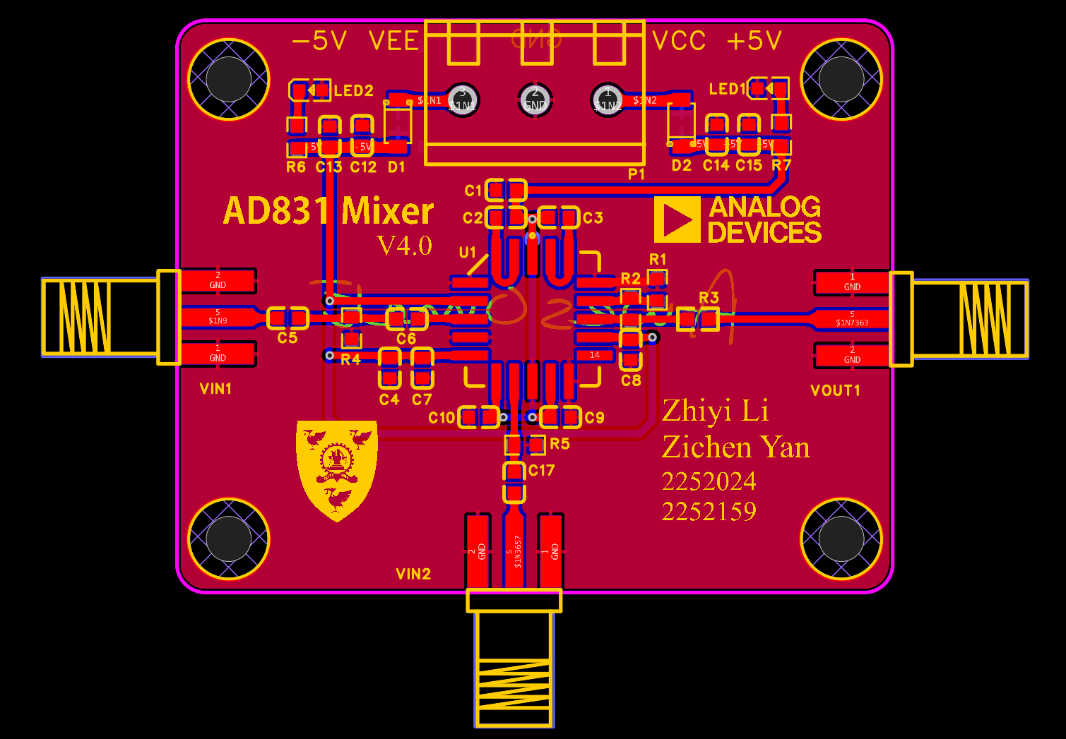
The RF input on the mixer board is three parts: a 220 pF in series from the SMA, a 51 Ω shunt to ground, and an 82 pF in series into the chip. When I built the board, impedance matching meant exactly what those three parts do: combine resistors, capacitors and inductors until the real parts on both sides are equal and the imaginary parts cancel. Drawing boards now, I keep running into a different version. USB differential pairs are drawn at 90 Ω and RF single-ended lines at 50 Ω, and those numbers don't come from components at all; they come from the stack-up, trace width, dielectric thickness and copper weight. Both are called impedance matching, and side by side they blur together very easily.
混频器板的 RF 输入端只有三个元件:SMA 进来串一颗 220 pF,对地并一个 51 Ω,再串一颗 82 pF 进芯片。做这块板的时候,阻抗匹配在我心里就是这三个元件干的事,把电阻、电容、电感凑一凑,让两边阻抗的实部相等、虚部抵消。现在画板子,又常碰到另一种说法:USB 差分线要做 90 Ω,射频单端线要做 50 Ω,这个数不靠元件凑,靠叠层、线宽、介质厚度和铜厚算。两样都叫阻抗匹配,放在一起很容易搅成一团。
Matching With Components元件搭出来的匹配
The first kind is about the impedances on the two sides of an interface. A source has an internal impedance, a load has its own, and if they differ part of the signal reflects at the boundary. The fraction is the reflection coefficient, Γ = (Z_L − Z_0) / (Z_L + Z_0). When the load equals the reference impedance, Γ is zero and all the power the source can deliver goes into the load. When the load isn't purely resistive, inductors and capacitors cancel its imaginary part and transform its real part to the reference value; the familiar L-section matching network does exactly that.
第一种匹配关心的是一个接口两边的阻抗。信号源有内阻,负载有阻抗,两者不相等,就有一部分信号在接口处被反射回去,反射的比例是反射系数 Γ = (Z_L − Z_0) / (Z_L + Z_0)。负载正好等于参考阻抗时 Γ 为零,信号源能送出的功率全部进到负载里。负载不是纯电阻时,就得用电感、电容把它的虚部抵掉,再把实部变换到参考阻抗上,常见的 L 型匹配网络就是干这个的。
The mixer board uses a blunter trick. The AD831's RF input is a class-A voltage-to-current stage driven by voltage. The datasheet gives about 1.3 kΩ of DC input resistance, and its input-impedance curve near 120 MHz reads roughly 800 Ω in parallel with about 3 pF. With 51 Ω in parallel in front of that, the 51 Ω sets the impedance almost on its own, and the source sees close to 50 Ω. The price is that most of the power burns in that resistor, but the chip only cares about the voltage on RFP, so the power is affordable.
混频器板上用的是更粗暴的一招。AD831 的 RF 输入是一个电压输入的 A 类电压电流转换级,数据手册给的直流输入电阻约 1.3 kΩ,输入阻抗曲线在 120 MHz 附近大约是八百欧并着三皮法左右的电容。51 Ω 并在它前面,阻抗基本由 51 Ω 决定,信号源看进来就接近 50 Ω。代价是功率大部分烧在这个电阻上,不过芯片要的是 RFP 上的电压,这点功率花得起。
Running the final input network with approximate values read off those curves, the impedance seen from the SMA comes to about 47.6 − j11.1 Ω: a reflection coefficient magnitude near 0.12, return loss close to 19 dB, and only 0.06 dB of mismatch loss. V1, with its two 10 nF capacitors, works out to 47.4 − j5.3 Ω by the same method, so it was already well matched. Swapping in 220 pF and 82 pF bought the two-stage high-pass at the cost of a little extra reactance, and the match barely suffered.
用手册曲线上读出的近似值,把最终版的输入网络算一遍,从 SMA 看进去约 47.6 − j11.1 Ω,反射系数的模约 0.12,回波损耗接近 19 dB,失配损耗只有 0.06 dB。V1 用的是两颗 10 nF,同样的算法得到 47.4 − j5.3 Ω,其实已经匹配得很好。后来换成 220 pF 和 82 pF,换来的是两级高通,代价只是多了一点虚部,匹配本身没有变差多少。
Characteristic Impedance of a Trace走线的特性阻抗
In the second kind, the conductor itself is the subject. A trace running over a solid ground has inductance and capacitance distributed along its length, and the square root of their ratio per unit length is its characteristic impedance, Z_0 = √(L′/C′). It depends on the trace width, the dielectric thickness to the reference plane, the permittivity and the copper thickness, and not at all on length. When a line is long enough, the signal travels along it and reflects at every change of impedance, so the line's Z_0 has to agree with both ends. The 50 Ω single-ended and 90 Ω differential figures in PCB work all refer to this.
第二种匹配的主角是导线本身。一根走线下面贴着完整的地,单位长度上就有分布电感和分布电容,两者之比开方,就是这根线的特性阻抗 Z_0 = √(L′/C′)。它由线宽、到参考地的介质厚度、介电常数和铜厚决定,和线有多长无关。线足够长时,信号沿着它传播,每到一处阻抗变化就反射一次,所以要让走线的 Z_0 和两端都对上。画 PCB 时说的单端 50 Ω、差分 90 Ω,指的都是这个。
A rough Hammerstad microstrip estimate puts a 50 Ω line on 1.6 mm FR-4 with a permittivity of 4.4 at about 3 mm wide. The widest trace on the mixer board is 0.762 mm, which under the same assumptions comes out near 100 Ω. I never calculated a trace width back then, and this one is a long way from 50 Ω.
按微带线的 Hammerstad 公式粗算,1.6 mm 厚、介电常数 4.4 的 FR-4 上,50 Ω 的微带线要做到 3 mm 左右宽。混频器板上最宽的走线是 0.762 mm,同样的条件下特性阻抗接近 100 Ω。当时没算过线宽,这个数离 50 Ω 差得很远。
Trace Length at 120 MHz120 MHz 下的走线长度
The board works anyway, and the reason is length. At 120 MHz, with an effective permittivity of about 3.3 for FR-4 microstrip, the wavelength is roughly 1.38 m. A common rule of thumb says a trace shorter than a tenth of a wavelength need not be treated as a transmission line (Baltic Lab gives this rule a quantitative look), which here means a dozen centimetres or more. The whole board is under 7 cm on a side, and SMA to RFP is two or three centimetres, an electrical length of only 5° to 7°.
差得远,板子照样能用,原因在于长度。120 MHz 在 FR-4 微带线上的波长,按有效介电常数 3.3 估,大约 1.38 m。常用的经验是走线短于波长的十分之一,就可以不当传输线看(Baltic Lab 对这条经验做过定量的讨论),这里对应十几厘米。整块板不到 7 cm 见方,SMA 到 RFP 也就两三厘米,电长度只有 5° 到 7°。
Putting 2 cm of 90 Ω line in front of the input network above changes the impedance seen from the SMA to about 46.8 − j5.1 Ω, hardly different from the network alone. On a board a few centimetres across at 120 MHz, component matching is enough, and keeping traces short with a solid ground is exactly the right thing to do in this band.
把一段 2 cm、90 Ω 的走线串在上面算出的输入网络前面,从 SMA 看进去的阻抗变成约 46.8 − j5.1 Ω,和不加这段线时差别很小。在 120 MHz、几厘米的板子上,元件那一种匹配已经够用,把线画短、把地铺完整,正好是这个频段该做的事。
The two kinds meet at the SMA connector. The coax that links the board to the instruments is itself a 50 Ω transmission line tens of centimetres long. With a velocity factor of about 0.7, a 120 MHz wavelength inside it is about 1.75 m, so a few tens of centimetres is a sizeable fraction of a wavelength and that stretch has to be treated as a line. The 51 Ω built from a component on the board sits right at the end of that 50 Ω coax and terminates it. The line's characteristic impedance sets the number to match, and the resistor on the board catches the signal where the line ends.
两种匹配在 SMA 头那里接上了头。接仪器用的同轴线本身就是 50 Ω 的传输线,几十厘米长,按同轴线约 0.7 的速度因子算,120 MHz 在里面的波长约 1.75 m,几十厘米已经占了波长里相当可观的一段,这段线必须按传输线来对待。板子上用元件凑出来的那个 51 Ω,正好接在这根 50 Ω 同轴线的末端,给它当终端。线的特性阻抗规定了要匹配到多少欧,板上的电阻负责在线的尽头把信号接住。