

2026-05-06
ULN2003A Electronic Expansion Valve Drive and Step ControlULN2003A 电子膨胀阀驱动与步进控制
An archive reading of the EEV driver board, ULN2003A schematic, STM32F103 phase mapping, blocking valve routines, and the thinner BLDC file trail.沿 EEV 驱动小板、ULN2003A 原理图、STM32F103 相线映射与阻塞式阀控制函数阅读一组历史归档,并标出较薄的 BLDC 文件线索。
ULN2003A Valve-Driver CircuitULN2003A 阀驱动电路
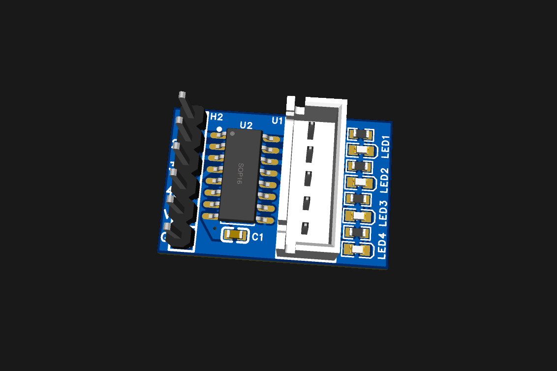
The EEV board render is small enough to read almost at a glance. A pin header marked H2 sits on one side, an SOP16 package marked U2 in the centre, a five-position connector opposite, and four LED positions along the output edge. The paired schematic supplies U2's identity as ULN2003A; the render shows placement, not an assembled board.
EEV 小板渲染很小,几乎一眼就能读完:一侧是标着 H2 的排针,中间是标为 U2 的 SOP16 封装,另一侧是一只五位连接器,四个 LED 位置沿输出侧排开。配套原理图才把 U2 标为 ULN2003A;渲染展示的是布局,并非装配成板。
The schematic fills in the path. H2 carries four input nets into 1B through 4B of the ULN2003A. The matching 1C through 4C nodes leave through pins 2-5 of the output connector, whose pin 1 is tied to VM. Each output node also meets an LED and 10 kOhm resistor branch. COM is drawn to VM, and a 100 nF capacitor is shown between the supply/common side and ground.
原理图把路径补完整:H2 的四路输入进入 ULN2003A 的 1B 到 4B,对应的 1C 到 4C 再从输出连接器 2-5 脚引出,连接器 1 脚接 VM。每条输出节点还接一支 LED 与 10 kOhm 电阻;COM 被画到 VM,供电 / 公共端一侧与地之间则画有 100 nF 电容。
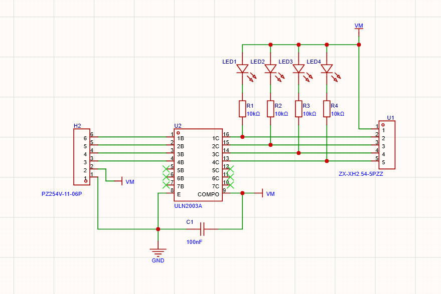
What is not drawn matters too. The sheet does not identify a valve model, supply value, coil current, connector rating, clamp behavior under a specific load, or measured waveform. The four LEDs express intended node indication in the drawing; only a hardware record could show whether the board drove a valve.
没画出来的部分同样重要:图里没有阀型号、供电数值、线圈电流、连接器额定值、特定负载下的钳位表现或实测波形。四个 LED 表达的是预期节点指示;板子是否带动过阀,只能由硬件记录回答。
GPIO Mapping and Eight-Step SequenceGPIO 映射与八拍驱动序列
The public CubeMX configuration names an STM32F103C8T6 and labels PB12-PB15 as valve phases A-D. The linked `solenoid-valve.c` maps those four pins to an eight-entry mask sequence: A, A+B, B, B+C, C, C+D, D, D+A. _apply_mask() writes set and reset bits through GPIOB BSRR, matching a four-phase low-side drive model.
公开的 CubeMX 配置写明 STM32F103C8T6,并把 PB12-PB15 标为阀相 A-D。链接中的 `solenoid-valve.c`把四个引脚映射到八项 mask 序列:A、A+B、B、B+C、C、C+D、D、D+A;_apply_mask() 再通过 GPIOB BSRR 同时置位与复位,对应四相低侧驱动模型。
The filenames still say “solenoid”, while the code expresses stepped position, full-open steps, homing, percent conversion, and a four-phase sequence. That mismatch is worth keeping visible: the implementation reads like a step-driven valve archive, not a simple on/off solenoid case.
文件名仍写着 “solenoid”,代码里却出现步进位置、全开步数、归零、百分比换算与四相序列。这个命名错位很值得保留:实现读起来更像步进阀归档,而不是简单的通断电磁阀案例。
Blocking Valve Control阀的阻塞式控制
The source defines Valve_StepNBlocking(), Valve_HomeBlocking(), Valve_MoveToStepsBlocking(), and Valve_MoveToUnit500Blocking(). In the linked `main.c`, startup calls Valve_Init(70), sets 530 full-open steps, and invokes blocking home. Encoder input changes a 0-500 set value; the ENC_BTN_EVT_SHORT branch commands a blocking move, while ENC_BTN_EVT_LONG calls soft home. K1/K2 store or recall two setpoints. OLED refresh is rate-limited to 30 ms when the UI is dirty, followed by a 2 ms loop delay.
源码定义了 Valve_StepNBlocking()、Valve_HomeBlocking()、Valve_MoveToStepsBlocking() 与 Valve_MoveToUnit500Blocking()。链接中的 `main.c`在启动时调用 Valve_Init(70),设定 530 个全开步数,再执行阻塞归零;编码器修改 0-500 设定值,ENC_BTN_EVT_SHORT 分支触发阻塞移动,ENC_BTN_EVT_LONG 分支调用软归零,K1 / K2 则保存或召回两组设定。UI 变脏时,OLED 刷新被限制到至少间隔 30 ms,循环末尾还有 2 ms 延时。
Those constants and calls are source facts, not calibration results. The archive has no matching valve specification, physical zero sensor, current trace, missed-step count, motion video, or timing capture. In particular, a function called HomeBlocking cannot prove that the mechanical zero was found repeatably.
这些常量与调用是源码事实,不是校准结果。归档没有配套阀规格、机械零点传感器、电流曲线、丢步统计、动作视频或时序抓取;尤其是一个叫 HomeBlocking 的函数,并不能证明机械零点可以重复找到。
BLDC Design FilesBLDC 设计文件
The same public folder also contains a quiet-fan BOM and an EasyEDA project. Their presence records a neighboring BLDC board direction, but no accompanying public render, schematic excerpt, topology description, voltage target, noise measurement, or bring-up log is present.
同一公开目录还放着一份静音风扇 BOM 与一个 EasyEDA 工程。它们记录了相邻的 BLDC 板卡方向,但没有配套渲染、原理图摘录、拓扑说明、目标电压、噪声测量或 bring-up 日志。
That leaves the archive with two different evidence strengths: the EEV side can be read from a board render, schematic, CubeMX configuration, and C source; the BLDC side currently stops at file presence. Neither side should be promoted into a current production or validated-performance claim.
所以这组归档存在两档证据强度:EEV 一侧可以沿渲染、原理图、CubeMX 配置与 C 源码阅读;BLDC 一侧目前停在文件存在。两边都不能被升级成当前生产状态或性能验证结论。