

2026-05-06
DHT11 and AM2302 Pinouts and Interface RequirementsDHT11 与 AM2302 的引脚定义与接口要求
An archived DHT board plan and the AM2302 manual expose a GND/NC conflict that must be resolved before approving a footprint or claiming verification.对读归档 DHT 小板计划与 AM2302 原厂手册,发现一处 GND / NC 冲突;批准封装或声称完成验证前,必须先解决这处冲突。
Sensor-Board Development Plan传感器小板开发计划
The archived PDF is a six-page development task plan for DHT11 and AM2302/DHT22 breakout boards. Its cover names another person as development owner and gives future board-release, soldering, and MCU-verification deadlines. Reviewing its interface constraints does not turn that assignment into personal board-design credit or a completed result.
归档 PDF 是一份六页的 DHT11 与 AM2302 / DHT22 小板开发任务计划。封面明确把另一位成员写作开发负责人,并列出后续发板、焊接与 MCU 验证截止日期。复核其中的接口约束,不会把那份分配任务变成个人板卡设计署名或完成结果。
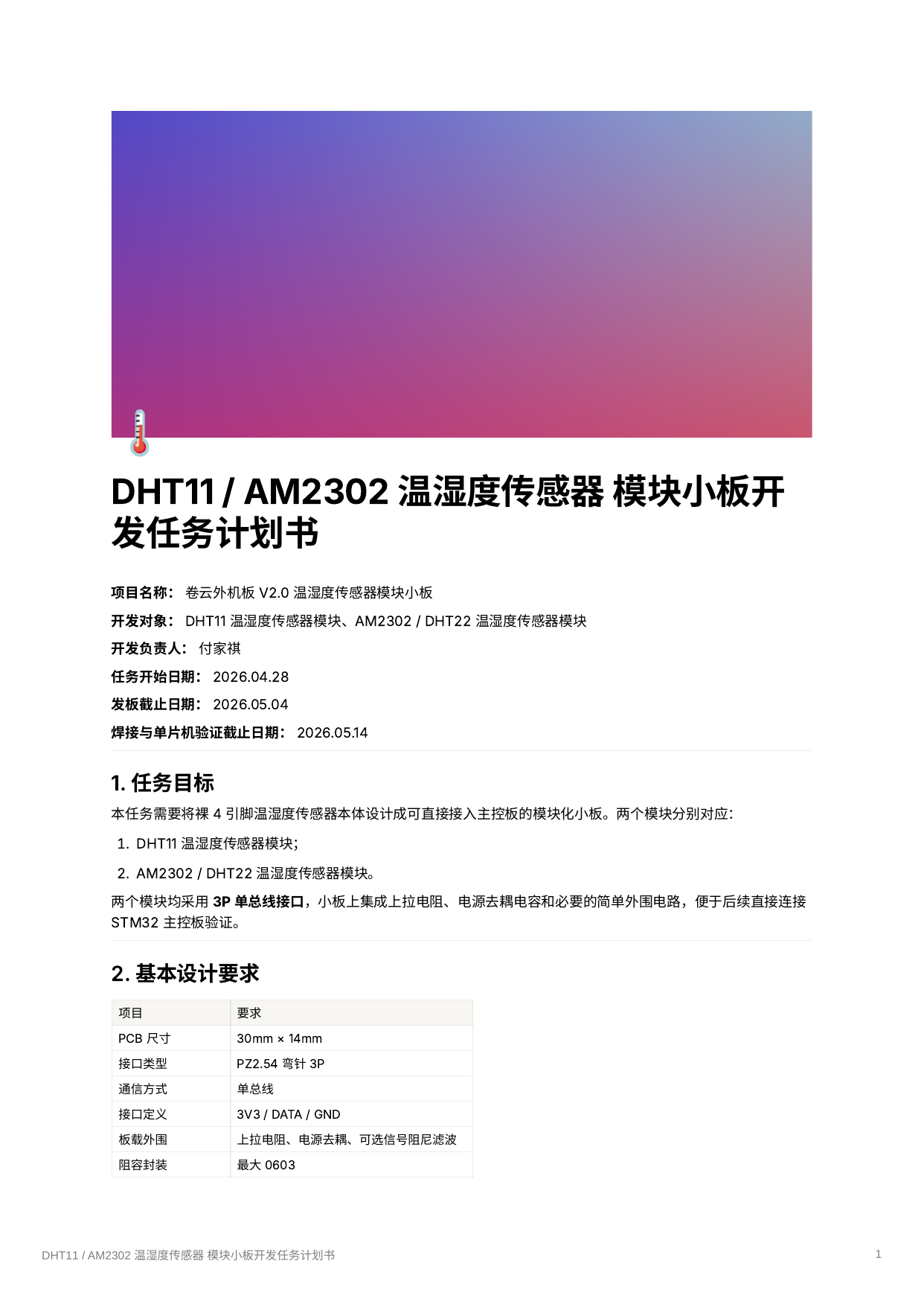
The full plan remains available here: DHT11 / AM2302 breakout-board task plan.
完整计划书保留在这里:DHT11 / AM2302 温湿度小板任务计划。
AM2302 Pin DefinitionsAM2302 引脚定义
The plan proposes the same host-side header for both boards: +3V3 / DATA / GND. Its sensor tables then assign DHT11 pin 3 to NC and pin 4 to GND, but assign AM2302 pin 3 to GND and pin 4 to NC. A warning below the tables says the two footprints cannot be exchanged.
计划书让两块板共用同一组主控侧接口:+3V3 / DATA / GND。接下来的传感器表格把 DHT11 pin 3 写成 NC、pin 4 写成 GND,却把 AM2302 pin 3 写成 GND、pin 4 写成 NC;表格下方还据此提醒两种封装不能混用。
The manufacturer's AM2302 technical manual gives a different AM2302 interface table: pin 1 VDD, pin 2 SDA, pin 3 NC, and pin 4 GND. That directly conflicts with the archived task plan's AM2302 row. The plan therefore cannot be used by itself to approve the sensor footprint.
AM2302 原厂技术手册给出的接口表却不同:pin 1 是 VDD,pin 2 是 SDA,pin 3 是 NC,pin 4 是 GND。这与归档任务计划中的 AM2302 行直接冲突,因此不能只凭任务书批准传感器封装。
The discrepancy does not show that a PCB was drawn with the wrong footprint, nor that anyone found and corrected it during the original task. It simply marks an issue that must be resolved against the exact sensor package and current manufacturer data before schematic capture or board release.
这处差异不能说明 PCB 曾经画错,也不能说明原任务中有人发现并修过它;它只标出一个必须在原理图绘制或发板之前,对照实际传感器封装与当前原厂资料解决的问题。
Pull-Ups, Supply, and Read Timing上拉电阻、供电与读取时序
The archived plan specifies a 4.7 kOhm DATA pull-up to 3.3 V and a 100 nF supply decoupling capacitor. It leaves a 1 uF supply capacitor and a 10 ohm DATA series resistor optional, while reserving a DATA-to-GND capacitor as DNP because excessive capacitance can slow the single-wire edge.
归档计划给 DATA 到 3.3 V 配了 4.7 kOhm 上拉与 100 nF 电源去耦;1 uF 电源电容和 10 ohm DATA 串联电阻为可选项,DATA 到 GND 的电容则默认 DNP,因为过大电容可能拖慢单总线边沿。
The AM2302 manual allows 3.3-5.5 V supply, recommends 5.0 V, gives about 5.1 kOhm as the typical pull-up for a lead shorter than 30 m, and limits a 3.3 V connection to no more than 1 m. The task plan's 3.3 V preference and 4.7 kOhm value are not automatically invalid, but supply drop, cable length, and logic-level compatibility need to be checked as one interface rather than copied from a table.
AM2302 手册允许 3.3-5.5 V 供电,推荐 5.0 V;线长小于 30 m 时,典型上拉约为 5.1 kOhm;使用 3.3 V 时,连接线又被限制在不超过 1 m。任务书偏好的 3.3 V 与 4.7 kOhm 并不会因此自动失效,但压降、线长与逻辑电平兼容性必须作为同一条接口一起核对,不能各抄一格就算完成。
Both documents call for at least two seconds after power-on before reading and at least two seconds between AM2302 reads. Those matching numbers strengthen the timing requirement, but still do not show that firmware or a physical board observed it.
两份文档都要求上电后至少等待两秒再读取,AM2302 两次读取间隔也至少两秒。数字在两边能对上,说明这条时序要求值得保留,却仍不能证明固件或实体板已经做到。
Board Dimensions and Mounting Clearance板框尺寸与安装间隙
The proposed board outline is 30 mm x 14 mm, with one M2 locating hole. The plan recommends a 2.2 mm hole, at least 4.5 mm keepout diameter, and at least 2 mm from hole edge to board edge. It also says the AM2302 body is about 15.4 mm wide, allowing the body to protrude slightly while the board remains 14 mm wide.
拟议板框是 30 mm x 14 mm,带一个 M2 定位孔;计划建议孔径 2.2 mm、keepout 直径至少 4.5 mm、孔边到板边至少 2 mm。它还写到 AM2302 本体约宽 15.4 mm,因此在保持 14 mm 板宽时允许本体轻微探出。
The sensor airflow opening and M2 mounting-hole clearance remain layout checks. For a future 3D preview, the plan specifically calls out connector direction and the AM2302 body's slight overhang. The PDF contains no reviewed 3D result, so these are requirements rather than confirmed clearances.
传感器通风开口与 M2 安装孔间隙属于布局检查。对于后续 3D 预览,计划书特别要求确认连接器方向与 AM2302 本体的轻微探出。PDF 没有附评审后的 3D 结果,因此这里记录的是要求,而不是已经确认的间隙。
MCU Tests and Acceptance RequirementsMCU 测试与验收要求
The plan's optional breadboard check asks for serial output, a response when a hand or breath changes the local environment, and five minutes without frequent read failures. Its final checklist repeats MCU reading, interval, and five-minute conditions, then requests schematic, PCB, Gerber, BOM, 3D view, soldering photos, and test records.
计划中的可选面包板检查要求串口输出、手靠近或吹气后环境读数产生合理变化,以及连续五分钟不频繁读取失败。最终验收清单又重复 MCU 读取、间隔与五分钟条件,并要求提交原理图、PCB、Gerber、BOM、3D 图、焊接照片与测试记录。
They are acceptance instructions, not acceptance evidence. None of those deliverables or logs is attached to this archive. The immediate engineering result of reading the plan is therefore narrower and more useful: resolve the AM2302 GND/NC conflict first, then verify the remaining electrical and mechanical assumptions before the board leaves paper.
这些都是验收指令,不是验收证据;当前归档没有附上上述交付物或日志。读完计划后,眼前真正得到的工程结论反而更窄也更有用:先解决 AM2302 的 GND / NC 冲突,再逐项确认其余电气与机械假设,最后才让小板离开纸面。